Design and simulation of Dual Band H Shaped Microstrip Patch Antenna for WLAN Applications
Poornanand Dubey 1
1 Assistant
Professor, Department of Electronics & Communication Baderia Global
Institute of Engineering & Management, Jabalpur (M.P.), India
|
|
|
ABSTRACT |
|
|
Nowadays,
microstrip patch antennas are very popular in radar and satellite
communication applications due to their low profile, mechanically robust,
relatively compact and small size, and the possibility of dual frequency
operation Unfortunately they have some limitations, especially narrow
bandwidth. This paper presents a new high gain, wide band H-shaped slot
loaded microstrip patch antenna. The antenna is printed on a dielectric
substrate, supported by a metal plate, and fed directly from a 50 Ω
coaxial cable. There are several and well known methods to increase the bandwidth of antennas
such as: use of substrate thickness, low electrode substrate, various
impedance matching and fading techniques In this paper, the bandwidth of
rectangular Microstrip antenna is increased by ‘H’ shaped rectangular
microstrip patch antenna. In some applications where increased bandwidth is
required, dual frequency patch antennas are one of the alternative solutions.
The proposed antenna has a dual frequency band. |
|||
|
Received 29 February 2024 Accepted 28 March 2024 Published 16 April 2024 DOI 10.29121/granthaalayah.v12.i3.2024.5933 Funding: This research
received no specific grant from any funding agency in the public, commercial,
or not-for-profit sectors. Copyright: © 2024 The
Author(s). This work is licensed under a Creative Commons
Attribution 4.0 International License. With the
license CC-BY, authors retain the copyright, allowing anyone to download,
reuse, re-print, modify, distribute, and/or copy their contribution. The work
must be properly attributed to its author.
|
|||
|
Keywords: H Shape, Patch, Patch Antenna, Substrate
Height |
|||
1. INTRODUCTION
Dual frequency operation of the antenna is very essential in today’s wireless communication system for some applications like GPS, WLAN etc. The proposed antenna provides dual frequency band The gain in the first frequency band (1.63-1.79 GHz) is 3.83dBi and the antenna efficiency About 98.96% and it's wi-fi It is suitable for applications. In the second-frequency band (2.4-2.3.34 GHz) the gain is 3.64dBi and the antenna efficiency is about 99.95% and is suitable for WLAN/Wi-MAX/Bluetooth applications [Khawaja (2013), Balanis (2005)] The proposed microstrip antenna of glass epoxy substrate Usage is designed using at 2.1 GHz operating frequency. The patch length and width of the proposed antenna are 32.4 mm and 43.4 mm, respectively. The microstrip antenna has established itself as a separate entity in the microwave antenna field because of its many advantages such as communication base stations, and radar, of small size, light weight, low profile, low cost, and ease of integration with other microwave components. Apart from a large variety of applications such as missiles, aircraft, satellite communications and mobile handsets It is also used in biomedical biometry services [Bhattacharya & Prasanna (2013)-Gupta (2013) The proposed H-shaped rectangular microstrip patch antenna has proven to be one of the effective methods in dual-frequency band operation. The proposed antenna is designed on a glass epoxy substrate (er =4.2) [Balanis (2005), Hong et al. (2006)]. The proposed Hshaped Microstrip antenna is fed by a 50Ω Microstrip feed line. A wide variety of wireless services have been successfully used worldwide for the last few years in modern communication systems and semiconductor technology development Antennas play a very important role in modern communication systems. Complexity is reduced and receiver performance is increased by a well-designed antenna. Depending on the application, the antenna dimension, type and configuration will be selected based on the operating frequency of the antenna [Li et al. (2002),Jayanthi & Nagaraja (2013)].
2. LITERATURE REVIEW
Broadband systems have been playing a very important role for wireless service requirements in wireless communication systems. Worldwide interoperability for Microwave Access (WiMAX)/ Wireless Local Area Network (WLAN) provides portable mobile broadband connectivity and offers a wireless alternative to cable and digital subscriber lines for (DSL) broadband access and it is accepted for mobile devices, laptops and smart Phones [Khawaja (2013)].
In modern wireless communication systems, multi-band antennas played a very important role for redundant service requirements [Hu et al. (2011)]. WLAN and WiMAX are now widely used in mobile devices such as handheld computers and smart phones. These two techniques are widely accepted as feasible, cost-effective, high-speed data connection solutions, enabling user mobility with the rapid development of modern wireless communication systems, antenna design has turned to focus on extensive multiband small and simple structures that It should be easy to imagine. WLAN and WiMAX environments suitable for WiMAX applications have grown rapidly to accommodate a complex variety. There are three operating bands for WiMAX technology called 2.4 GHz (2.5 - 2.8 GHz) low band, 3.2 GHz (3.2 -3.8 GHz) medium-band, and 5.3 GHz (5). .2 - 5.8 GHz) are called high-band respectively, because, WiMAX Offering multiband operation, microstrip patch antennas are highly preferred. Microstrip patch antennas are popular due to their low cost, small size, light weight and easy fabrication [Balanis (2005),Bhattacharya, & Prasanna (2013)].
In this paper, a dual band H-slot microstrip patch antenna is designed, optimized and simulated. The antenna covers two frequency bands: 3.6-3.7 GHz and 5.7-5.8GHz. The proposed antenna can find applications in several communication standards used in WiMAX/WLAN [Zhang et al. (2006)].
Antennas are important components in communication systems, playing a role in transmitting and receiving signals. In modern wireless communication systems, multi-band antennas played a very important role for redundant service requirements [Gupta (2013)]. Now satellite and mobile communication systems have widely required multi-band capacity antennas to meet increasing system complexity Rapid development of modern wireless communication focuses antenna manufacturing on wide multiband and small simple structures that can be easy to build. Multiband, low profile, and low cost antennas are widely used [Balanis (2005), Hong et al. (2006)]. In this paper, a compact circularly polarized rectangular panel with a circular slot antenna is proposed. Circularly polarized antennas have the advantage of reducing losses due to polarization mismatches between the signals and the receiving antenna. A well-known method of generating circular polarization is to create different sizes of radiating elements with a feed, such as a rectangular strip with cut corners In this proposed antenna is used to feed the microstrip line method to be a universal design. This proposed an antenna design on single layer, single feed, and dual band frequency of the antenna. The proposed antenna designed on FR-4 substrate, is compacted in size 21.1 32 1.6 mm2. This antenna is operated at 5.5 GHz. [Li et al. (2002), Jayanthi & Nagaraja (2013)]
This antenna was designed for various applications such as low band is used for Wireless Local Area Network (WLAN) and high band is used for television broadcasting, radar, satellite communication etc. Details and experimental results of the designed antenna are presented. Microstrip patch antennas are widely used in wireless application because of their great advantages such as low profile, high transmission efficiency, light weight, low profile, conformal and planar structure, compactness, low cost, and ease of integration with microwave circuitry. Because of the benefits happens now a days for personal and business purposes Compact microstrip antennas are receiving much more attention due to the increase in the demand for small size antennas used A higher dielectric constant of the substrate should be used to fabricate compact microstrip antennas at fixed operating frequency [Lee et al. (2013),Yang & Kishk (2008)].
To reduce the size of the antenna and improve its efficiency, one more method applying the bending method on the ground plane of the microstrip antenna reduces the fundamental resonance frequency of the antenna compared with the same expensive patch bending method. The impedance bandwidth and antenna gain can be increased, which is a great advantage of such a ground curve method over the patch meandering method A high gain or wide bandwidth antenna can be realized by stacking parasitic patches in a microstrip patch antenna. These characteristics of a stacked microstrip antenna depend on the distance between the feed patch and the parasitic patch. When the distance is about 0.1λ (wavelength), the stacked microstrip antenna has a wide bandwidth [Kamarudin et al. (2013),Islam et al. (2008)].
Various methods have been adopted to increase the bandwidth of microstrip antennas such as increasing substrate thickness, using low electroconstant substrates, using various feeding techniques and impedance matching of slot antenna geometry and polyresonators. However we have found dual band with good efficiency and radiation characteristics.This paper presents a microband patch antenna with dual band parallel slots giving dual bandwidth of 12.50% & 6.76%. Radar and GPS systems, use micro strip antennas because of its advantages and make them popular. This structure of the antenna is simple tomanufacture and versatile in nature and it is proposed to perform operations that include circular polarization and dual or triple band operation with a wide to minor frequency ratio [Kracchhodnok & Wongsan (2013)].
The primary advantage of this method is the manufacturing case as the design does not require alignment between multiple layers of metal and dielectric material. The antenna has considerable freedom to control the dual design frequencies. This includes applications such as WCDMA 3G [Singh et al. (2013)]. It is derived that the resonant frequency is inversely proportional to slot length and feed point and increases with increasing coaxial probe feed radius and slot width In recent years Dual/triple band using single/double U slots in microstrip antenna There were some letters reported for operation. It can be seen that applications that require dual-frequency operation with a low frequency ratio were designed using U-slots in wideband microband antennas Microband antennas suffer from low impedance bandwidth characteristics to enhance wideband applications. Various bandwidth enhancement techniques such as coplanar parasitic patches, stacked patches, or new shape patches such as U and H -shaped patches have been developed to avoid this distress of the antennas It is said, that of the strip To avoid the use of coplanar or stacked parasitic patches that compensate for natural impedance variations, we can perform an etching process on the patch with U -slots, which increases the lateral size or thickness of the antenna and therefore, sometimes with increased impedance bandwidth, microstrip patches -More than one by changing the current distribution above The resonant frequency is obtained. In 1995, two scientists named Huynh and Li presented a wideband single-layer probe-fed patch antenna with a U -shaped slot on a rectangular patch surface [Zhang et al. (2006), Chitra et al. (2012)]. In this paper, we present a rectangular microband patch antenna. Let's build in which to increase its bandwidth and frequency response in fine band patches U-shaped slots are cut
Many communication standards, such as WiMAX, are now being developed for high-frequency and high-speed communication. This rapid growth in communication standards has created a great demand for multi-band broadband antennas of low real estate, low cost construction, and ease of integration with feed networks Over the past decades, microstrip, slot to implement multi-band. In this paper, we proposed and presented a quad band H-slot microstrip patch antenna for WiMAX/WLAN application. A coaxial probe is connected to a rectangular strip that is located near the center of the rectangular H-slot patch for better excitation of the proposed antenna over a wide bandwidth. The antennas are 3.41-3.51 GHz, 4.64-4.75 GHz, .45-5.63 GHz, It covers four frequency bands such as 6.38-6.50 GHz. [Pathak et al. (2012)-Thakare & Singhal (2009)].
3. ANTENNA DESIGN
First, we choose the substrate which is the first step in the design of the patch antenna. Teflon (doped electrical constant = 1.33 and height = 3.175mm) is used as substrate to design the proposed H-slot microstrip patch antenna. These values have been carefully chosen to meet our performance and bandwidth requirements because the dielectric material is important for determining the performance of the antenna A thin substrate is required to achieve compactness but as the height decreases the bandwidth of the antenna decreases.
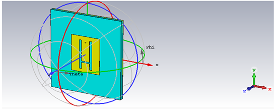
The dielectric constant of the substrate is closely related to the size and bandwidth of the microstrip antenna. A low electrical constant of the substrate leads to a larger bandwidth, while a high electrical constant of the substrate leads to a smaller size of the antenna A trade-off exists between antenna size and bandwidth. The following figure shows the patch antenna in its original form: a flat plate on the ground plane (usually a PC board). The center conductor of the coax acts as a feed probe to couple the electromagnetic energy to the band and/or outside. Also indicated is the electric field distribution of a rectangular plate excited in its fundamental mode. The electric field is zero in the center of the strip, maximum (positive) on one side and minimum (negative) on the opposite side. Notably, the minimum and maximum continuously change aspects according to the instantaneous phase of the applied signal. The electric field does not stop abruptly at the periphery of the cavernous panel, but the fields extend the outer perimeter to some extent.
Figure 1
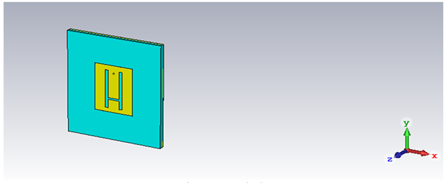
|
Figure 1 Analysis |
4. ANTENNA PARAMETERS
t1=1.3
d2="3.3479" "Feed Outer Diameter"
d1="1" "Feed Inner Diameter"
c="9" "Distance of 3rd centre H-slot from edge"
b="3" "Distance of Slot from edge"
a="2.1" "Slot gap"
Yf="5.6" "Feed Y-cordinate"
Xf="0" "Feed X-cordinate"
Ws="12" "Width of Slot"
Wg="67" "Substrate length in X-direction"
W="27" "Width of Patch in X-direction"
Tm="0.03" "Patch thickness"
Ls="27.25" "Length of Slot"
Lg="74" "Substrate length in Y-direction"
L="34" "Length of \\patch in Y-direction"
H="3.6" "Substrate height"
Er="1.33" "Substrate dielectric constant"
5. RESULTS AND DISCUSSION
The proposed rectangular microstrip antenna was successfully studied and since the proposed antenna has dual frequency band, it is suitable for many applications. The narrow bandwidth of the microstrip antenna is a critical feature that restricts its wide use. From the above it is clear that the H-shaped patch antenna which provides dual frequency operation and high return loss. The VSWR of the antenna is between 1 to 2 over the entire frequency band which shows good impedance matching. The simulation performance of the proposed micro strip patch antenna has been analyzed using CST simulation software version 19.
Figure 2
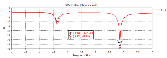
|
Figure 2 S Parameter |
Figure 3
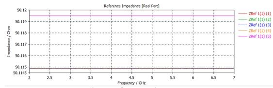
|
Figure 3 Reference Impedance |
Figure 4
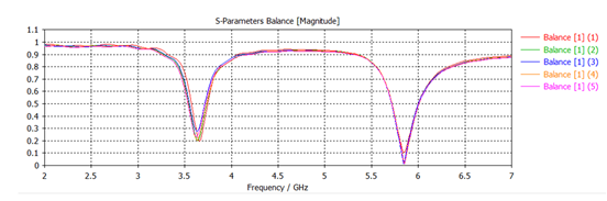
|
Figure 4 S Parameter balance |
Figure 5
|
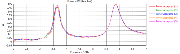
Figure 5 Power in W (Accepted) |
Figure 6
|
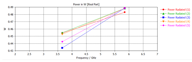
Figure 6 Power in W (Radiated) |
Figure 7
|
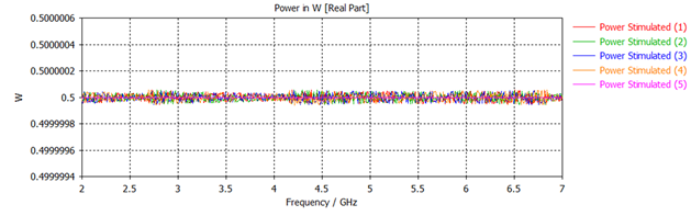
Figure 7 Power in W (Simulated) |
Figure 8
|
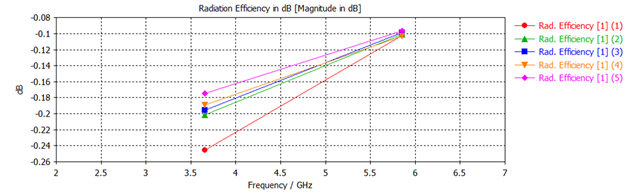
Figure 8 Radiation Efficiency |
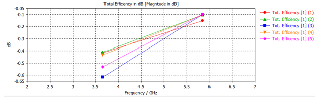
Figure 9
|
Figure 9 Total Efficiency |
Figure 10
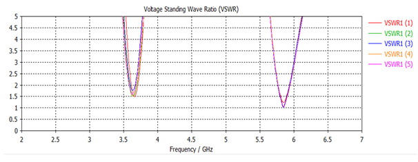
|
Figure 10 VSWR |
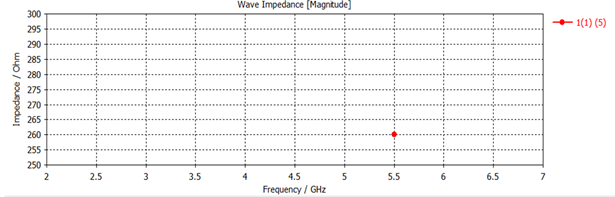
Figure 11
|
Figure 11 Wave Impedance |
Figure 12
|
Figure 12 Far Field |
6. CONCLUSIONS
A new technique to enhance the bandwidth of a microstrip patch antenna having dual band characteristics and wide bandwidth capability for specific applications has been successfully designed and discussed, the antenna provides dual frequency. The characteristics of dual band H-slot microstrip patch antenna are analyzed through various parametric studies using CST software. The antenna has achieved good impedance, stable radiation pattern. The antenna has a return loss of -12.413 dB at 3.6154 GHz and -39.919 dB at 5.851 GHz. The simulated result of the designed antenna shows good performance and this type of antenna is used in various applications such as satellite.
CONFLICT OF INTERESTS
None.
ACKNOWLEDGMENTS
None.
REFERENCES
Amman, M. (1997). Design of Microstrip Patch Antenna for the 2.4 GHz Band. Applied
Microwave and Wireless, 24-34.
Balanis, C. A. (2005). Antenna Theory: Analysis and Design (2nd ed.). Wiley-Interscience.
Balanis, C. A. (2005). Antenna
Theory: Analysis and Design.
John Wiley & Sons, Inc.
Bhattacharya, D., & Prasanna, R. (2013). Bandwidth Enrichment for Microstrip Patch Antenna Using Pendant Techniques. International Journal of Engineering Research (IJER), 2(4), 286-289.
Chitra, R. J., Jayanthi, K., & Nagaraja, V. (2012). Design of Double U-slot Microstrip Patch Antenna Array for WiMAX. In IEEE International Conference on Green Technologies (ICGT) (130-134). https://doi.org/10.1109/ICGT.2012.6477960
Garg, R. (2001). Microstrip Antenna Design Handbook. Artech House.
Gupta, H. (2013). Design and Study of
Compact and Wideband Microstrip U-Slot Patch Antenna for WI-Max Application.
IOSR Journal of Electronics and Communication Engineering (IOSR-JECE), 5(2),
45-48. https://doi.org/10.9790/2834-0524548
Hong, J.-S., McErlean, E. P., & Karyamapudi, B. (2006). Eighteen-pole superconducting CQ filter for future wireless applications. IEE Proceedings on Microwave Antennas and Propagation, 153, 205-211. https://doi.org/10.1049/ip-map:20050043
Hu, C.-L., Yang, C.-F., & Lin,
S.-T. (2011). A Compact Inverted-F
Antenna to be Embedded in
Ultra-thin Laptop Computer for LTE/WWAN/WI-MAX/WLAN
Applications. IEEE Transactions on Antennas and
Propagation (AP-S/USRT), 978-1-4244-9561.
Islam, M. T., Shakib, M. N., Misran, N., & Yatim, B. (2008). Analysis of Broadband Slotted Microstrip Patch Antenna. IEEE Transactions on Antennas and Propagation, AP-1-4244-2136.
Jayanthi, K., & Nagaraja, V. (2013). Design of Microstrip Slot Antenna for WiMAX Application. In IEEE International Conference on Communications and Signal Processing (ICCSP) (645-649). https://doi.org/10.1109/iMac4s.2013.6526489
Jayanthy, T., Sugadev, M., Ismaeel, J. M., & Jegan, G. (2008). Design and Simulation of Microstrip M-Patch Antenna with Double Layer. IEEE Transactions on Antennas and Propagation, AP-978-1-4244-2690-4444. https://doi.org/10.1109/AMTA.2008.4763102
Kamarudin, M. R., Rahman, T. A., & Iddi, H. U. (2013). Multi-band Circular Patch Antenna for Wideband Application. In PIERS Proceedings (1584-1587).
Khawaja, M. (2013). Dual Band
Microstrip Patch Antenna Array for Next Generation Wireless Sensor Network
Applications. In International Conference on Sensor Network Security Technology
and Privacy Communication System (SNS & PCS) (39-43). National University
of Sciences and Technology. https://doi.org/10.1109/SNS-PCS.2013.6553831
Kracchhodnok, P., & Wongsan, R.
(2013). Design of a Dual-band Antenna using a Patch and Frequency
Selective Surface for WLAN and WiMAX. In International Conference on Electrical
Engineering/Electronics, Computer, Telecommunications and Information
Technology (ECTI-CON) (1-4). https://doi.org/10.1109/ECTICon.2013.6559631
Lee, K.-F., Elsherbeni, A. Z., & Driessen, P.
(2013). Wide Band Dual-Beam U-Slot Microstrip Antenna. IEEE Transactions
on Antennas and Propagation, 61(3), 1415-1418.
https://doi.org/10.1109/TAP.2012.2228617
Li, K., Ingram, M., & Rausch, E. (2002).
Multibeam antennas for indoor wireless communications. IEEE Transactions on
Communications, 50(2), 192-194. https://doi.org/10.1109/26.983314
Nasir, S. A., Mustaqim, M., & Khawaja, B. A.
(2013). Dual U-Slot Triple Band Microstrip Patch Antenna for Next
Generation Wireless Networks. In International Conference on Sensor Network
Security Technology and Privacy Communication System (SNS & PCS) (1-6).
https://doi.org/10.1109/ICET.2013.6743490
Pathak, R. S., Singh, V. K., & Ayub, S.
(2012). Dual Band Microstrip Antenna for GPS/ WLAN/ WiMAX
Applications. International Journal of Emerging Technology and Advanced Engineering (IJETED), 7(2).
Singh, P., Chandel, A., & Naina, D. (2013). Bandwidth Enhancement of Probe Fed Microstrip Patch Antenna. International Journal of Electronics and Communication Technology (IJECCT), 3(1).
Sze, J. Y., & Wong, K. L. (2001).
Bandwidth enhancement of a microstrip-line-fed printed wide slot antenna. IEEE
Transactions on Antennas and Propagation, 49(7), 1020-1024.
https://doi.org/10.1109/8.933480
Thakare, V. V., & Singhal, P. (2009). Neural network based CAD model for the design of rectangular patch antennas. Journal of Engineering and Technology Research (JETR), 1(7), 129-132.
Yang, L. S., & Kishk, A. A. (2008). Dual- and Multiband U-Slot Patch Antennas. IEEE Antennas and Wireless Propagation Letters, 7, 645-647. https://doi.org/10.1109/LAWP.2008.2010342
Zhang, Q., Meng, Q., Sun, L., Huang, J., Wang,
Y., Zhang, X., He, A., Li, H., He, Y., & Luo, S. (2006). A
high-performance ultra-narrow bandpass HTS filter and its application in a
wind-profiler radar system. Superconductor Science and Technology, 19,
S398-S402. https://doi.org/10.1088/0953-2048/19/5/S49
 This work is licensed under a: Creative Commons Attribution 4.0 International License
© Granthaalayah 2014-2024. All Rights Reserved.