
|
|
|
|
STUDY OF SURFACE FINISH AS A FUNCTION OF CERAMIC TOOL WEAR WHEN TURNING HARDENED AISI 52100 STEEL
Jean Carlo Cescon Pereira 1![]() , Vinícius Chiaradia Pereira 1
, Vinícius Chiaradia Pereira 1
1 Institute of Mechanical Engineering,
Federal University of Itajuba, Brazil
|
|
|
ABSTRACT |
|
|
The turning
process in hard materials has been way more used in the last few years
because of the demand to reduce the manufacturing cost. This research
analyzes the superficial roughness evolution in mixed ceramic tool`s wear
used to turn ABNT 52100 hardened steel. This study has the objective to find
the major reasons that influence the flank wear in ceramic insert and analyze
how this wear influences the samples superficial roughness. In the turning
process the variables cutting speed (Vc), feed (f)
and machining depth (ap) were changed during the tests and analyzed their
influences in superficial roughness. The experiments show that the greatest tool
wear, for the variables used, was because of the forward speed. In the
superficial finish study the only thing which has a great impact in average
roughness (Ra) was the forward speed that when elevated has increased the
average roughness. Meanwhile the vibration excess, caused by the machine`s
low hardness, mainly for the several cutting properties, caused damage to the
cutting tool that helped to increase the roughness rate while the flank wear
also advanced. |
|||
|
Received 05 July 2025 Accepted 02 August 2025 Published 13 September 2025 Corresponding Author Jean
Carlo Cescon Pereira, cescon@unifei.edu.br DOI 10.29121/ijetmr.v12.i9.2025.1668 Funding: This research
received no specific grant from any funding agency in the public, commercial,
or not-for-profit sectors. Copyright: © 2025 The
Author(s). This work is licensed under a Creative Commons
Attribution 4.0 International License. With the
license CC-BY, authors retain the copyright, allowing anyone to download,
reuse, re-print, modify, distribute, and/or copy their contribution. The work
must be properly attributed to its author.
|
|||
|
Keywords: Turning
Process, Ceramic Tools, Flank Wear, Roughness |
|||


1. INTRODUCTION
Usually,
the process of chip removing materials that are between 45 to 68 HRC is called
a hard turning process Bartarya and
Choudhury (2012). A few years ago, the hardened
materials which the turning process needed to be worked by the retification process. According to Diniz et
al. (2014), the retification
operations and the turning process of the hardened materials could be compared
in technical terms and also in the actual manufacturing scenery therefore the
turning process gains are significant in both situations. In contrast to the retification the costs of the turning process in hardened
materials can be reduced by over 60% because of the low machine-tool cost, as
well the reduced time and more flexibility of the process. Changing the retification process to the hardened turning process brings
many advantages, among the possibilities is to work without cutting fluid, the
possibility to skip some steps, higher production, low uses of energy for
processed material volume, low costs machine-tools and also the possibility to
do many operations in the same setup, which guarantees the geometrics
characteristics and reduces the operation time.
Among the
different types of tools that are used in hardened turning, this work choosed to use the ceramic tools because of its high
hardness properties when working with high temperatures and high strength to
natural wear and also for the low cost when compared to CBN or PCBN. The choice
for the wet turning was because of the fact that in this condition the cutting
in high temperatures increases the chip deformation and shear, reducing the
cutting strengths. Wet conditions also avoid handling problems, maintenance and
disposal problems which pollute the environment and human health too Wins and Varadarajan (2011).
About hardened materials tooling, it is possible to realize the cutting
strength isn't necessarily high. It is because of the chip´s plastic
deformation which is relatively small and also because of the small area of
contact between the tool and the piece, which reduces the friction strength Nakayama
and Kanda (1988). According to Abrão et
al. (1995), tolling the ABNT 52100 steel (62
HRC) with PCBN and mixed ceramic, was possible to realize that during the
superficial finish process, the passive strength (radial) was bigger than
others strength’s components, the reason is related to smaller position angle (χr) caused by the small deep tooling
value in relation to the to the tool nose radius. Nakayama
and Kanda (1988) says: turning a steel for bearing
in two different types of heat treatment annealed 23 HRC and hardened 62 HRC), it
was possible to observe that the value of the forward strength was bigger than the
strength in both cases for an angle from 0 to 60 degrees. In the turning
process, the superficial finish has great importance because it is directly
related to the piece’s functioness because it is also
related to the wear resistance and fatigue, friction coefficient, corrosion
resistance and lubrication Singh
and Rao (2007). According to the He et al. (2018) it is possible to have in CNC
turning machines a roughness from a that is what is generally expected.
A fact
that has big influence on roughness and so in superficial finish of the pieces
is the tool’s corner geometry Thiele
and Melkote (1999) and Özel et al. (2005), which suffers with big varieties
as long as the tool’s flank wear increases Zhou et al. (2004) and Binder
et al. (2017). About the superficial finish in
the turning process, Sata (1985) verified that not always the gain
achieved is increased by the tool’s tool nose radius (geometric influence)
which is translated to a better superficial finish for the piece because will
increase the tool nose radius and also the strengths involved in the process
and consequently in the vibrations of the system. As König
and Wand (1988) says that the increase of the
cutting and the forward strengths demand a lot from the machine-tool to
provides high power, meanwhile the passive strength’s increases causing ELASTIC
deformations of the system machine-tool-piece and also local ELASTIC deformations
near to the point of cutting, so it can cause to the piece wrongs geometrics
dimensions and even broking the tool. In the study of tool’s life and average
superficial roughness using the turning process, there are many factors that
influence, for example the cutting speed, the feed rate and the deep cutting.
2. MATERIALS AND METHODS
The
turning tests were dimensioned to proportionate a clear and accurate way to
study speed cut, feed and machining depth influence in mixed ceramics tool`s
wear and surface finish as well. To determine the tool`s end life was admitted
flank wear Vbmax=0,3 mm. This criterion was admitted
because above this value starts the risk of breaking the tool`s ceramic insert,
besides that it represents a big value, when it happened the cutting edge
became really damaged.
The
experiments were done in a Turning CNC Nardini Logic 175 center. Mixed changing
ceramics inserts (Al2O3 + TiC), Sandvik GC 6050 class
roofed with Titanium Nitride (TiN) with ISO CNGA
120408 S01525 geometry chamfered. The test pieces used in the analysis were
fabricated with AISI 52100 steel (Villares) and then heat treated to increase
the hardness. It is shown in Table 1 the AISI 52100 steel chemical
composition.
Table 1
|
Table 1 AISI 52100 Chemical Composition |
||||||||
|
Chemical
Composition (% weight) |
||||||||
|
Element |
C |
Si |
Mn |
Cr |
Mo |
Ni |
S |
P |
|
Concentration |
1,03 |
0,23 |
0,35 |
1,40 |
0,04 |
0,11 |
0,001 |
0,01 |
After heat
treatment the testing pieces showed 55 HRC average hardness until a deep 3,0
mm. The pieces were Ø49 x 104 mm of dimension and split in 2 parts of 50 mm
length each.
The takes of
average roughness (Ra) were done using a Taylor Hobson rugosimeter, model Surtronic 3+,
calibrated before the takes. The flank wear (Vbmax)
over the tool`s surface gap was monitored using microscopic optical
photographs. The flank wear photos on the gaps surface were done with an image analyzer, which has an optic microscope that can zoom from
25 to 50 times linked to a camera plugged to a microcomputer.
During
the tests two levels of variety were admitted for each parameter of tooling. It
is shown in Table 2 three variables: cutting speed,
feed and machining depth, and also shows the levels of variation for each
parameter. The range of variations was changed respecting the manufacturer’s
recommendations.
Table 2
|
Table 2 Machining Parameters Used |
||||
|
Machining
Parameters |
||||
|
Parameter |
Simbol |
Unit |
Lower Level |
Higher Level |
|
Cutting speed |
Vc |
m/min |
200 |
240 |
|
Feed |
f |
mm/rotação |
0,05 |
0,10 |
|
ap |
mm |
0,15 |
0,30 |
|
|
Machining
depth |
||||
3. RESULTS AND DISCUSSIONS
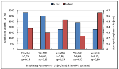
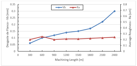
In the Figure 1 is shown the machining length (Lc)
done by the mixed ceramic’s edge for each condition utilized and the respective
value of average roughness (Ra) when achieved the full lifetime of
tool use, the value stipulated was Vbmax=0,3
mm for flank wear. At the experiments the parameters speed cutting (Vc) was varied from 200 m/min to 240 m/min, feed
(f) from 0.05 mm/v to 0,10 mm/v and machining depth (ap) between
0,15 mm and 0,30 mm, which the tests utilized mixed ceramic covered with
Titanium Nitride.
Figure 1
|
Figure 1 Cutting Edge Machining Lengths and Respective Average Roughness Values When Reaching the End of Tool Life Criterion. |
The cutting conditions where the machining
parameters are in the lowest level (Vc=200 m/min;
f=0,05 mm/rotation; ap=0,15 mm) shows the longest machining length done by the
cutting edge until achieving the lifetime end parameter. For the harshest
cutting situation where all the parameters are in the highest level (Vc=240 m/min; f=0,10 mm/rotation; ap=0,30 mm), the cutting
edge did the shortest length until achieving 0,3 mm flank wear.
For the parameters that have the most influence in
tool’s lifetime, it is possible to realize that increasing the feed levels
provokes bigger wear and reduces tool’s lifetime, represented by the shortest
machining length done by the cutting edge. In sequence, in descending order of
influence, appears machining depth and cutting speed, besides the condition
that all the other parameters are in their highest levels. It is crucial to
observe, though, for the fact that these results are relevant only for tooling
tempered AISI 52100, machined with mixed ceramic tools (Al2O3 + TiC), covered with TiN (geometry:
ISO CNGA 120108 S01525) and also with the cutting parameters variating in the
level ranges already mentioned in this work.
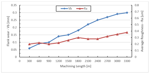
In the Figure 2 is shown the average roughness behavior (Ra) related to the evolution of the
flank wear (Vbmax) of the tool’s cutting
edge for the test using the parameters in the lowest levels.
Figure 2
|
Figure 2 Roughness Behavior in Relation to the Progression of Flank Wear for the Condition Vc=200 m/min, fz=0,05 mm/V e ap=0,15 mm. |
Is
possible to realize that for this machining condition the roughness maintains
between 0,2 to 0,38 µm, increasing as far as the flank wear increases. For
gentle conditions of tooling the cutting edge achieves the longest length for
the tests, validating the results found in literature. This happens because of
the low heat generation and also of the system’s low levels of vibration due to
lower cutting effort.
Grzesik
(2008) analyzed
the effects of the tool’s wear in surface roughness during the tooling process
of hardened steel using ceramic tools. The results show an increase in average
roughness as far as the flank wear increased. Raising the cutting speed to Vc=240 m/min and keeping the other parameters in the lowest
levels was possible to see a small reduction in machining length as shown in Figure 3. The roughness continues inside
a good range of values, varying between 0,15 to 0,30 µm and progresses slowly
as far as the flank wear increases. The reduction in length machining happens
because of the high temperatures at the cutting area due to a bigger cutting
speed which favors a bigger level of wear at the
cutting edge.
Figure 3
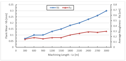
|
Figure 3 Roughness Behavior in Relation to the Progression of Flank Wear for the Condition Vc=240 m/min, fz=0,05 mm/V e ap=0,15 mm. |
The
increase of the cutting speed provided a small improvement in roughness behavior because of a more dynamic cutting due to a higher
speed.
In Figure 5 it is shown the behavior of the flank wear and average roughness to
increase in the machining feed from a 0,05 mm/rotation to 0,10 mm/rotation. It
was expected that increasing the feed would also increase the average roughness
during all the machining length due to a bigger cutting tool displacement
between subsequent rotations. However, increasing the feed caused a great
decrease of the machining length, decreasing to 50% of the value achieved with
its lowest feed level. For this cutting parameter the tool’s cutting edge broke
when achieved the flank wear Vbmax=0,25
mm, so the lifetime ended before the expected.
Figure 4
|
Figure 4 Roughness Behavior in Relation to the Progression of Flank Wear for the Condition Vc=200 m/min, fz=0,10 mm/V e ap=0,15 mm. |
This
cutting edge broke probably due to a bigger vibration of the system
machine/tool/piece because of the highest cutting strengths happened by the
feed increase. The turning CNC used for this work has low stiffness and this
also relates to the fact that the ceramic tool has low tenacity. This
combination makes the tool suffer with little chips due to bigger vibration and
cutting strengths, breaking the tool.
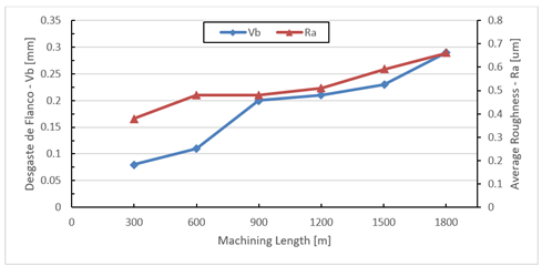
In Figure 5 it is possible to see that
increasing the machining depth has a small influence in machining length,
providing a smaller decrease compared to what the cutting speed increase provided.
The roughness showed lower values of all tests done keeping its value around
0,20 µm during all the machining length. A small reduction in machining length
relative to a condition with all the parameters in the lowest level, the
significant wear increase from 1800 m machining length as well. probably
happens due to bigger cutting strengths consequently bigger system’s
vibrations. Otherwise, the increase of the machining depth provided low
roughness values. This shows that the biggest tool’s penetration contributed to
a better surface finish bringing better results like the results by increasing
the tool nose radius.
Figure 5
|
Figure 5 Roughness Behavior in Relation to the Progression of Flank Wear for the Condition Vc=200 m/min, fz=0,05 mm/V e ap=0,30 mm. |
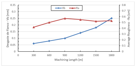
For
the condition with all the machining parameters in the highest values, it is
possible to observe a new reduction in machining length, as shown in Figure 6. This behavior
is similar to what happened in the test of increasing the feed. This fact
confirms the thesis that the machining feed provides biggest cutting strengths
and consequently increases the system’s vibration damaging faster the ceramic
tool’s cutting edge causing small chips deformation. It is also possible to
observe an increase of the average roughness, that has direct relation to the
flank wear increase and the feed in its highest value as well.
Figure 6
|
Figure 6 Roughness Behavior in Relation to the Progression of Flank Wear for the Condition Vc=240 m/min, fz=0,10 mm/V e ap=0,30 mm. |
In
his study about the influence of the tool’s wear in the surface roughness
tooled, Pavel et
al. (2005) reported that with the
progression of wear, all the roughness parameters studied increased.
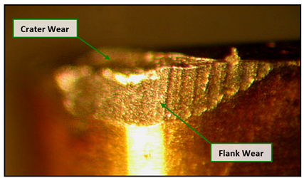
For
all the conditions, were verified mostly the flank and the crater wear, with
some chip’s occurrence. As shown in Figure 7 where the parameters Vc, f and ap were in their lowest values, the tool’s wear
was uniform, observing a crater wear and an increasing flank wear that
progressed until achieving the lifetime Vbmax=0,3 mm.
Figure 7
|
Figure 7 Tool Wear After Reaching End-of-Life Criteria for Vc=200 m/min, f=0,05 mm/v e ap=0,15 mm. |
In Figure 7 is shown vertical wear marks
that evidence the occurrence of wear of mechanical abrasion. As much the
frontal wear as the crater wear can be caused by abrasion, but the abrasion
stands out on frontal wear due to friction of surface gap with a hard element,
that is the piece, while the exit surface is in touch to the flexible element,
which is the chip. This type of wear is caused by the hard particles of the
piece’s materials and by the cutting temperature that reduces the tool’s
hardness.
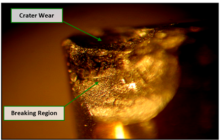
An
example of tool breaking is in Figure 8. This breaking occurred for Vc=200 m/min; f=0,10 mm/v; ap=0,15 mm, where is visible the
most important factor in reducing the lifetime of the tool, the feed, in its
highest level. In Figure 8 observe a high crater wear that
occurred at the exit surface of the tool, caused by the friction between the
tool and the chip. This break happens when the crater wear progresses until
reaching the flank wear, in this case the situation was amplified by the
turning machine’s lack of hardness.
Figure 8
|
Figure 8 Tool Breakage for the Condition Vc=200 m/min, f=0,10 mm/v e ap=0,15 mm. |
In
the experiments were observed occurrences of chip and break at the cutting
edge, mainly for the several conditions of machining. In these conditions
became more pointed the cutting strengths and system’s vibration, caused as
much by the high machining speed as by the lack of turning machine’s hardness.
Another reason that can contribute to the chip occurrence and breaks is the
fact that the turning process was done with ceramic tools, which, due to its
low tenacity and high hardness, became extremely sensitive to vibrations from a
system with lower hardness.
4. CONCLUSIONS AND RECOMMENDATIONS
Tests
of turning process were carried under various conditions using AISI 52100
hardened steel. The purpose of these tests was to determine tooling’s
parameters influences over the behavior of the
roughness and also over the machining length, and the behavior
of the roughness in relation to the progression of the flank wear as well. The following conclusions can be drawn:
·
The
factors cutting speed (Vc), feed (f) and machining
depth (ap) wield significantly influence over the machining length traveled by the tool until reaching the lifetime criterion,
which each one contributes to the reduction of cutting tool’s lifetime.
·
Among
the factors analyzed, the greatest influence wielded
over the machining length traveled by the tool was
because of the feed, following by the machining depth and finally by the
cutting speed.
·
In
the studies of surface finish, the unique factor that wielded great influence
on the average roughness (Ra) was the feed, which when always increased
provided an increase in average roughness.
·
For
feed f= 0,05mm/rotation, it is possible to achieve average roughness values
equals to values of conventional ratification process, but with a feed f=0,10
mm/rotation this value (Ra ≤ 0,40 µm) was sometimes exceeded.
· The excess of vibration caused by the machine’s lack of hardness, mainly for the most severe cutting conditions, provoked damages to the cutting tools, like small and big chipping and even breaking the cutting edge, being responsible to the lifetime end.
CONFLICT OF INTERESTS
None.
ACKNOWLEDGMENTS
The authors are grateful to CNPq and Fapemig for their support on this research and the resources dispensed to realize this work.
REFERENCES
Abrão, A. M., Aspinwall, D. K., & Wise, M. L. H. (1995). Tool Wear, Cutting Forces and Temperature Evaluation When Turning Hardened Bearing Steel Using PCBN and Ceramic Materials. In Proceedings of the Thirty-First International Matador Conference (pp. 209–216). Manchester. https://doi.org/10.1007/978-1-349-13796-1_33
Bartarya, G., & Choudhury, S. K. (2012). State of the Art in Turning. International Journal of Machine Tools and Manufacture, 53(1), 1–14. https://doi.org/10.1016/j.ijmachtools.2011.08.019
Binder, M., Klocke, F., & Doebbeler, B. (2017). An Advanced Numerical Approach on Tool Wear Simulation for Tool and Process Design in Metal Cutting. Simulation Modelling Practice and Theory, 70, 65–82. https://doi.org/10.1016/j.simpat.2016.09.001
Diniz, A. E., Marcondes, F. C., & Coppini, N. L. (2014). Material Machining Technology (6th ed.). São Paulo: Artliber Publisher.
Grzesik, W. (2008). Influence of Tool Wear on Surface Roughness in Hard Turning Using Differently Shaped Ceramic Tools. Wear, 265(3–4), 327–335. https://doi.org/10.1016/j.wear.2007.11.001
He, C. L., Zong, W. J., & Zhang, J. J. (2018). Influencing Factors and Methods of Theoretical Modeling of Surface Roughness in the Turning Process: State of the Art. International Journal of Machine Tools and Manufacture, 129, 15–26. https://doi.org/10.1016/j.ijmachtools.2018.02.001
König, W., & Wand, T. H. (1988). Turning Bearing Steel with Amborite & Ceramic. Industrial Diamond Review, 47(3), 117–120.
Nakayama, K., Arai, M., & Kanda, T. (1988). Machining Characteristics of Hard Materials. Annals of the CIRP, 37(1), 89–92. https://doi.org/10.1016/S0007-8506(07)61592-3
Özel, T., Hsu, T., & Zeren, E. (2005). Effects of Cutting Edge Geometry, Workpiece Hardness, Feed Rate and Cutting Speed on Surface Roughness and Forces in Finish Turning of Hardened AISI H13 Steel. International Journal of Advanced Manufacturing Technology, 25(3–4), 262–269. https://doi.org/10.1007/s00170-003-1878-5
Pavel, R., Marinescu, I., Deis, M., & Pillar, J. (2005). Effect of Tool Wear on Surface Finish for a Continuous and Interrupted Hard Turning Case. Journal of Materials Processing Technology, 170(1–2), 341–349. https://doi.org/10.1016/j.jmatprotec.2005.04.119
Sata, T. (1985). Analysis of Surface Roughness Generation in Turning Operation and its Applications. Annals of the CIRP, 34, 473–476. https://doi.org/10.1016/S0007-8506(07)61814-9
Singh, D., & Rao, P. V. (2007). A Surface Roughness Prediction Model for Hard Turning Process. International Journal of Advanced Manufacturing Technology, 32(11–12), 1115–1124. https://doi.org/10.1007/s00170-006-0429-2
Thiele, J. D., & Melkote, S. N. (1999). Effect of Cutting Edge Geometry and Workpiece Hardness on Surface Generation in the Finish hard Turning of AISI 52100 Steel. Journal of Materials Processing Technology, 94(2–3), 216–226. https://doi.org/10.1016/S0924-0136(99)00111-9
Wins, K. L. D., & Varadarajan, A. S. (2011). An Environment Friendly twin-jet Minimal Fluid Application Scheme for Surface Milling of Hardened AISI 4340 Steel. International Journal of Manufacturing Systems, 30–45. https://doi.org/10.3923/ijmsaj.2011.30.45
Zhou, J. M., Andersson, M., & Ståhl, J. E. (2004). Identification of Cutting Errors in Precision Hard Turning Process. Journal of Materials Processing Technology, 153–154, 746–750. https://doi.org/10.1016/j.jmatprotec.2004.04.331
|
|
 This work is licensed under a: Creative Commons Attribution 4.0 International License
© IJETMR 2014-2025. All Rights Reserved.