
|
|
|
|
Modeling and Optimization of Peristaltic Fluid Transport in Axisymmetric, Porous Structures
Dr. Curtis Boodoo 1![]()
![]()
1 Utilities
and Sustainable Engineering, The University of Trinidad and Tobago, Trinidad
and Tobago
|
|
|
ABSTRACT |
|
|
Peristaltic
transport, a fundamental physiological and engineering process, involves the
movement of fluid through a distensible tube via sequential compression and
relaxation. This study investigates the peristaltic transport of an
incompressible Newtonian fluid in an axisymmetric, porous, corrugated tube,
emphasizing the interplay between fluid dynamics and the tube's structural
characteristics. Utilizing lubrication theory and perturbation analysis
within a wave frame of reference, we explore the effects of hydraulic
resistivity, geometric parameters of the corrugation, and porous layer
thickness on the phenomena of trapping and circulation. Our findings reveal
that hydraulic resistivity significantly influences the development of
circulation regions within the fluid core, which has implications for the
efficiency of mixing and nutrient absorption in biological and industrial
applications. Additionally, the geometric configuration of the wavy porous
layer—specifically its amplitude and thickness—critically impacts the
formation of trapping and circulation regions, thereby affecting fluid
transport efficiency. This work not only advances our understanding of
peristaltic pumping mechanisms but also highlights the potential for
optimizing fluid transport processes in both biological systems and
industrial applications. The insights gained from this study contribute to
the design of more efficient peristaltic pumps and offer a valuable framework
for future research aimed at enhancing substance delivery and mixing through
peristaltic transport. |
|||
|
Received 08 January 2024 Accepted 10 February 2024 Published 22 February 2024 Corresponding Author Dr.
Curtis Boodoo, curtis.boodoo@utt.edu.tt
DOI 10.29121/ijetmr.v11.i2.2024.1407 Funding: This research
received no specific grant from any funding agency in the public, commercial,
or not-for-profit sectors. Copyright: © 2024 The
Author(s). This work is licensed under a Creative Commons
Attribution 4.0 International License. With the
license CC-BY, authors retain the copyright, allowing anyone to download,
reuse, re-print, modify, distribute, and/or copy their contribution. The work
must be properly attributed to its author.
|
|||
|
Keywords: Peristaltic
Transport, Porous Media, Circulation, Nutrient Absorption, Brinkman, Darcy |
|||


1. INTRODUCTION
Peristaltic transport is the movement of fluid achieved by alternating compression and relaxation along a distensible tube, which propels the fluid. The principle of peristaltic transport of fluid is extensively utilized in industrial and commercial pumps. Peristaltic pumps use rotating rollers pressed against a distensible tube, creating a pressurized flow. The fluid is moved through the tube with each rotating motion. The major advantage of a peristaltic pump is that the only contact the fluid being pumped has with the peristaltic pump is in interior of the distensible tube. This allows isolation of the fluid from the environment of the pump and is essential in the case of sterilized or hazardous fluid being transported Gupta & Gupta (2007).
Peristaltic transport of fluid is common within the human body. Example of this include: urine flow from the kidney to the bladder, swallowing through the esophagus, movement of chyme in the gastro-intestinal tract, intra-uterine fluid motion, flow of spermatozoa in the ductus efferentes of the male reproductive tract, movement of ovum in the female fallopian tube, transport of lymph in the lymphatic vessels and the vasomotion of small blood vessels such as arterioles, venules and capillaries Shit et al. (2010). Earthworms also use peristalsis as a means of locomotion.
The current study will focus on peristaltic transport in the human body, in particular transport in the gastro-intestinal tract and capillaries. Epithelial cells line major cavities and organs of the body. These include the stomach and small intestine, kidney, pancreas, and esophagus. Epithelial cells also form the structure of the lung. The epithelial cells that line capillaries are referred to as endothelial cells. Epithelial cells serve many functions which include transportation and absorption of nutrients. Absorption of nutrients by epithelial cells is accomplished by a process called transcytosis. Transcytosis occurs as membrane-bound carriers selectively transport materials between one part of the cell and another to maintain unique environments on either side of the cell Barnes et al. (2008). The selective absorption of nutrients or materials by epithelial cells facilitates modeling epithelial cells as porous media. This motivates the formulation of the current model.
Early studies in peristaltic pumping was carried out by Shapiro et al. (1969). They investigated peristaltic pumping under small Reynolds number and a large tube aspect ratio to allow uniform pressure distribution over the tube cross section. They presented results for varying geometric parameters and introduced, explained, and illustrated reflux flow. They also referred to an experiment that confirmed their findings. They applied their model for peristaltic pumping to the gastro-intestinal system.
Barton & Raynor (1968) explored the case where the wall disturbance wavelength is much larger than the average tube radius, and when the disturbance wavelength may be as small as the average radius. They used numerical techniques to determine the relation between average flow rate and pressure differential across a wavelength.
Wei et al. (2003) investigated pressure driven flow of a Newtonian fluid in a two dimensional wavy, poro-elastic, cartesian walled channel. Biphasic mixing theory is employed for the poro-elastic layer and the flow is solved by a lubrication approximation using the aspect ratio of the channel. They obtained the velocity fields using a perturbation approach and discussed the fluid flow and geometrical parameters that develop and influence trapping or recirculation eddies within the Newtonian fluid.
Mishra & Rao (2008) studied peristaltic transport in an axisymmetric tube, with a Brinkman porous peripheral region and a Newtonian fluid core region, using the lubrication approach. They allowed for deformation of the porous-fluid interface by determining the interface as part of the solution using the conservation of mass in both the porous medium and fluid medium separately. They used a shear stress jump condition at the interface between the peripheral and core regions. Pumping characteristics, trapping, and reflux phenomena are discussed for various parameters governing the flow.
In this present study, peristaltic transport of an incompressible Newtonian fluid in an axisymmetric, porous, corrugated, or wavy tube is investigated. The porous layer is modelled as a Darcy region with a transition Brinkman layer. The analysis is performed in a wave frame of reference. Lubrication theory as well as perturbation analysis is used to solve the velocity field and pressure. The boundary conditions used at the Brinkman-fluid interface include jump in tangential stress, continuity or normal stresses and continuity of radial and axial velocities. The boundary conditions at the Brinkman-Darcy interface include the Beavers and Joseph boundary condition and continuity of normal stresses. The phenomena of reflux or recirculation is observed and its dependency on the fluid flow parameters of hydraulic resistivity, tangential stress jump and the Darcy slip parameter is studied from streamline and velocity field plots.
2. MODEL FORMULATION
Peristaltic pumping is modeled as the motion of an infinite wave train along an axis symmetric porous cylindrical tube. The tube core is filled, and the porous layer saturated with the same incompressible viscous Newtonian fluid. The equation of the infinite wave train at the outer walls of the porous media, in cylindrical polar coordinates is given by:
![]()
where ![]() : is the constant velocity of the wave train
to the right in the
: is the constant velocity of the wave train
to the right in the ![]() direction and
direction and ![]() is the amplitude of the wave train. The
thickness of the porous region is denoted by
is the amplitude of the wave train. The
thickness of the porous region is denoted by ![]() .
The porous region is modeled using Darcy's equation. A Brinkman transition
layer is used between the Darcy region and the core fluid to allow for better
matching between the core Newtonian fluid and the Darcy porous region. The
thickness of the Brinkman transition layer is represented by
.
The porous region is modeled using Darcy's equation. A Brinkman transition
layer is used between the Darcy region and the core fluid to allow for better
matching between the core Newtonian fluid and the Darcy porous region. The
thickness of the Brinkman transition layer is represented by ![]() .
.
The equation representing the Core - Brinkman interface is:
![]()
The equation representing the Brinkman - Darcy interface is:
![]()
Figure 1

|
Figure 1 Wave Train in
Fixed Frame of Reference. |
Following the analysis of Shapiro
et al. (1969), the fixed frame of
reference coordinates ![]() and
and ![]() and axial velocity
and axial velocity ![]() and radial velocity
and radial velocity ![]() are transformed to the corresponding wave
frame of reference variables
are transformed to the corresponding wave
frame of reference variables ![]() and
and ![]() by performing the following transformations:
by performing the following transformations:
![]()
In the fixed frame of reference, the outer wall of the
Darcy region, moves with velocity ![]() ,
towards the right. In the wave frame of reference, the wave train appears
stationary, and the outer wall of the Darcy region appears to move leftward
with velocity
,
towards the right. In the wave frame of reference, the wave train appears
stationary, and the outer wall of the Darcy region appears to move leftward
with velocity ![]() .
.
2.1. Governing Equations - the Core and Porous region
2.1.1. Dimensionless Analysis
The analysis is performed on the wave frame of reference. Following a similar analysis to Wei et al. (2003) the dimensionless quantities are:
![]()
For the pressure p:

Where ![]() is the characteristic volumetric flow rate per
unit depth into the tube,
is the characteristic volumetric flow rate per
unit depth into the tube, ![]() the density of the fluid and
the density of the fluid and ![]() and
and ![]() the viscosity of the fluid in the core and the
porous regions respectively.
the viscosity of the fluid in the core and the
porous regions respectively.
The aspect ratio ![]() is defined as:
is defined as:
![]()
And Reynolds number ![]() is given by
is given by
![]()
The interfaces ![]() and
and ![]() and the porous wall
and the porous wall ![]() are dimensionless and given
are dimensionless and given
by:

For simplicity, the hats are dropped from the dimensionless variables in the analysis that follows.
2.1.2. Dimensionless Core region
In this region, we use the continuity equation:
![]()
and the Navier Stokes equation:
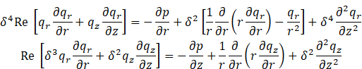
2.1.3. Dimensionless Brinkman Region
In the Brinkman region ![]() and
and ![]() represent the radial and axial velocities
respectively.
represent the radial and axial velocities
respectively. ![]() represents the pressure,
represents the pressure, ![]() represents the volume fraction of
represents the volume fraction of
the fluid in the porous layer and ![]() .
The dimensionless hydraulic resistivity
.
The dimensionless hydraulic resistivity ![]() is defined in terms of the Darcy permeability
parameter
is defined in terms of the Darcy permeability
parameter ![]() .
.
![]()
The equations are:

![]()
2.1.4. Dimensionless Darcy region
In the Darcy region ![]() and
and ![]() represents the radial and axial velocities
respectively and
represents the radial and axial velocities
respectively and ![]() represents the pressure. The equations are:
represents the pressure. The equations are:

2.1.5. Dimensionless Boundary Conditions
The boundary conditions for the interfaces ![]() and
and ![]() are now specified in non dimensional form.
are now specified in non dimensional form.
At ![]()
1) The
axial core velocity ![]() and the radial core velocity
and the radial core velocity ![]() are finite.
are finite.
At ![]()
Jump in tangential stresses:
![]()
where ![]() is the stress jump parameter.
is the stress jump parameter.
2) Continuity of normal stresses:
![]()
3) Continuity of radial and axial velocities:
![]()
At ![]()
1) Beavers and Joseph boundary condition on the axial velocity.
![]()
where ![]() is the dimensionless parameter from Beavers
and Joseph condition.
is the dimensionless parameter from Beavers
and Joseph condition.
2) Continuity of normal stresses:
![]()
At ![]()
1) There is no penetration of the radial velocity at the outer wall.
![]()
2) There is a non zero negative axial velocity Shapiro et al. (1969)
![]()
The total characteristic volumetric flow rate along the
tube is given by, ![]() ,
where
,
where ![]() is the characteristic volumetric flow rate per
unit depth. By definition Chhabra
& Richardson (2008):
is the characteristic volumetric flow rate per
unit depth. By definition Chhabra
& Richardson (2008):
![]()
Writing Eq3.3.24 in dimensionless form dropping the superscript hats:
![]()
2.1.6. Asymptotic Expansion
The geometry of the tube and the wave train is such that
the average wavy variation of the wave train is small along the axial
direction. The aspect ratio ![]() .
A perturbation series in
.
A perturbation series in ![]() is now employed for the flow field variables.
is now employed for the flow field variables.
![]()
![]()
The dimensionless governing equations and the
corresponding boundary conditions do not contain expressions in ![]() ,
again following an analysis similar to Wei
et al. (2003), the perturbation
series first order term is in
,
again following an analysis similar to Wei
et al. (2003), the perturbation
series first order term is in ![]() .
Collecting the leading order and first order terms gives the corresponding
leading order and first order systems.
.
Collecting the leading order and first order terms gives the corresponding
leading order and first order systems.
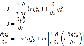
2.1.7. Leading Order System
Core region:
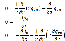
Brinkman region:
Darcy Region:
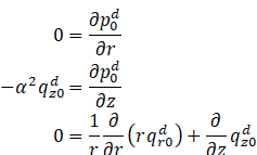
Boundary
Conditions:
2.1.8. Solution to the leading order system
Core region
![]()
Brinkman region
![]()
Darcy region
![]()
where the terms: ![]() and
and ![]() are all functions of
are all functions of ![]()
2.1.9. Obtaining the Constants
The boundary conditions are now applied and expressions
for the constants ![]() and
and ![]() are obtained.
are obtained.

where:
![]()

3. RESULTS AND DISCUSSIONS
The analytical expressions obtained for the stream functions and velocities for the different regions is now presented in their corresponding domains. These domains are complex two-dimensional regions, which comprises sinusoidal boundaries. The regions are meshed, using a triangular mesh, and the co-ordinates of each node substituted into the analytical expression for the stream function to obtain the velocity field and stream function plots that follow.
Figure 2

|
Figure 2 Triangular
Meshing for the Different Domains |
The analysis that follows is done in the wave frame of
reference. The ratio, ![]() .is
given by Einstein's law of viscosity
.is
given by Einstein's law of viscosity ![]() Goyeau et al. (2003).
The thickness of the transition Brinkman layer
Goyeau et al. (2003).
The thickness of the transition Brinkman layer ![]() is the average pore size of the porous medium Goharzadeh et al. (2005)
is the average pore size of the porous medium Goharzadeh et al. (2005)
The values of the other constants used are:
![]()
It should be noted that from ![]() and
and ![]() the radial velocity in the Darcy region
the radial velocity in the Darcy region ![]() and the axial velocity in the Darcy region
and the axial velocity in the Darcy region ![]() hence in the Darcy region there is only a
axial velocity.
hence in the Darcy region there is only a
axial velocity.
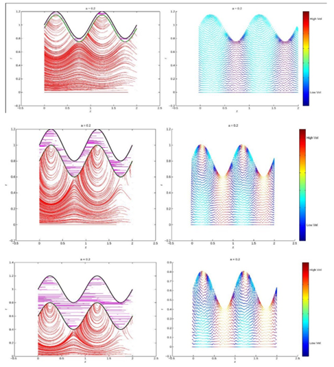
In the streamline plots that follow, the fluid core region streamlines are red, the thin transition Brinkman layer is green and the Darcy region has purple streamlines. The color of the arrows in the velocity field plots represents velocity magnitudes. Dark blue represents the lowest velocities and red the highest velocities.
Figure 3

|
Figure 3 Streamlines
(Top Pair) and the Corresponding Velocity Field (Bottom Pair) for α –
250 and 10:(a=0.2,α_j=1.45,β=1.47,ϵ_2=┤ 0.02,ϕ=0.4,ϵ_1=0.2,
and ϵ_3=0.05 ) |
Figure 4

|
Figure
4 Core Region Streamlines and
Velocity Fields for Varying a:(β= 1.47, α=50,α_j=1.45,ϵ_2=0.02,ϕ=0.4,ϵ_1=0.2
and ├ ϵ_3=0.05) |
Figure 5
|
Figure
5 Core Region Streamlines and
Velocity Fields for Varying ϵ_1:(β= 1.47,α=50,α_j=1.45,ϕ=0.4,a=0.2
and ├ ϵ_3=0.05) |
3.1. Discussion
Trapping and
Circulation as ![]() is
varied.
is
varied.
The phenomena of trapping was discussed by Shapiro et al. (1969). They defined trapping as the region of fluid having a mean speed of advance equal to the wave speed. The fluid is hence trapped in that it moves at least in the mean, with the wave itself. In the trapping region there is a recirculation of fluid particles.
Trapping is observed in the fluid core region of the
streamlines and velocity field plots for varying hydraulic resistivity ![]() ,
Figure 3. The values of
,
Figure 3. The values of ![]() ,
chosen for the plots satisfies the range of values of
,
chosen for the plots satisfies the range of values of ![]() ,
given by Wei
et al. (2003) for capillaries in the
human body. In the fluid core region, for
,
given by Wei
et al. (2003) for capillaries in the
human body. In the fluid core region, for ![]()
![]() and
10, the streamlines under the peaks of the porous region bend upwards,
representing the circulating path that the fluid particles in this region
assume. This is confirmed in the corresponding velocity field plots, Figure 3, where under the
porous peaks there is a circulating velocity field. This result is different
from that presented by Wei
et al. (2003), where they observed
circulation inside the peaks of the poroelastic region, which they modeled
using mixing theory. Circulation regions, in the core fluid, under the peaks of
the porous region was observed by Mishra
& Rao (2008). They used a Brinkman
model for the porous region and under the lubrication approach assumed the
radial velocity
and
10, the streamlines under the peaks of the porous region bend upwards,
representing the circulating path that the fluid particles in this region
assume. This is confirmed in the corresponding velocity field plots, Figure 3, where under the
porous peaks there is a circulating velocity field. This result is different
from that presented by Wei
et al. (2003), where they observed
circulation inside the peaks of the poroelastic region, which they modeled
using mixing theory. Circulation regions, in the core fluid, under the peaks of
the porous region was observed by Mishra
& Rao (2008). They used a Brinkman
model for the porous region and under the lubrication approach assumed the
radial velocity ![]() of the core region to be negligible. Hence the
circulation regions they observed were solely due to the fluid core region,
axial velocity
of the core region to be negligible. Hence the
circulation regions they observed were solely due to the fluid core region,
axial velocity ![]() and not the superposition of
and not the superposition of ![]() and
and ![]() as presented here. When
as presented here. When ![]() ,
the circulation region increases in size to almost the entire radius of the
tube.
,
the circulation region increases in size to almost the entire radius of the
tube.
It is important to study the magnitude of the velocity fields, given by the colors of the field arrows. Within the circulation regions, the fluid velocity is at its slowest, this is illustrated by the blue color of the velocity field. Fluid or in the case of the human body, material, or nutrients, in this region, circulate at a slow speed or have a greater resident time. This allows for more efficient mixing and absorption of nutrients into the porous region underneath the peaks. Wei et al. (2003) commented that the circulation regions they observed inside the peaks of the poroelastic region allows a greater resident time for fluid particles near the adjacent trough. This is not the case for the core fluid in this model, in fact from the velocity field plots, the troughs adjacent to the circulating peak regions have a higher velocity than the circulating fluid.
Geometric effects
on trapping and circulation.
From Figure 4, the amplitude ![]() of the wavy porous region affects trapping. An
increase in α
increases the trapping region under the porous peaks. From the velocity field
plots, as
of the wavy porous region affects trapping. An
increase in α
increases the trapping region under the porous peaks. From the velocity field
plots, as ![]() is increased, there is a greater separation of
lower velocity regions under the porous peaks. This result matches that of Pozrikidis (2005) and the comments of Wei et
al. (2003).
is increased, there is a greater separation of
lower velocity regions under the porous peaks. This result matches that of Pozrikidis (2005) and the comments of Wei et
al. (2003).
Affects of porous
layer thickness, ![]()
Porous layer thickness ![]() affects circulation and trapping. This is
illustrated in Figure 5. For
affects circulation and trapping. This is
illustrated in Figure 5. For ![]() the circulation region under the porous peaks
increases in size. When
the circulation region under the porous peaks
increases in size. When ![]() the circulation regions maintains,
approximately, a fixed size, but with the increase in porous layer thickness,
the circulation region is pushed downwards towards the center of the tube.
the circulation regions maintains,
approximately, a fixed size, but with the increase in porous layer thickness,
the circulation region is pushed downwards towards the center of the tube.
4. CONCLUSIONS And RECOMMENDATIONS
This study has explored the intricate dynamics of peristaltic transport of an incompressible Newtonian fluid within an axisymmetric, porous, corrugated tube, utilizing a comprehensive analytical framework that incorporates porous layer theory and perturbation analysis. Our investigation reveals the critical role of hydraulic resistivity, geometric parameters of the wavy porous structure, and the porous layer thickness in shaping the transport characteristics, particularly in terms of trapping and circulation phenomena.
The study demonstrates that the hydraulic resistivity parameter, α, plays a pivotal role in the formation of circulation regions within the fluid core, with significant implications for the efficiency of mixing and nutrient absorption processes. This finding not only corroborates the observations made by previous studies but also extends our understanding by highlighting the influence of the Brinkman model in capturing the nuances of fluid behavior in the core region adjacent to the porous peaks.
Furthermore, the geometric configuration of the wavy porous layer, especially its amplitude and thickness, is shown to have a profound impact on the trapping and circulation regions. An increase in the amplitude of the wavy porous region amplifies the trapping phenomenon, while the thickness of the porous layer dictates the extent and positioning of circulation regions, thereby affecting the overall transport efficiency within the tube.
This work contributes significantly to the body of knowledge on peristaltic pumping, particularly in the context of biological and industrial applications where the isolation and precise control of fluid transport are paramount. The insights garnered from our model underscore the potential of peristaltic transport mechanisms to optimize fluid flow and enhance the delivery and mixing of substances, whether in medical devices, industrial processes, or within the human body.
CONFLICT OF INTERESTS
None.
ACKNOWLEDGMENTS
None.
REFERENCES
Barnes, P. J., Drazen, J. M., Rennard, S. I., & Thomson, N. C. (2008). Asthma and COPD: Basic Mechanisms and Clinical Management. Academic Press.
Barton, C., & Raynor, S. (1968). Peristaltic Flow in Tubes. The Bulletin of Mathematical Biophysics, 30(4), 663–680. https://doi.org/10.1007/BF02476682
Chhabra, R. P., & Richardson, J. F. (2008). Non-Newtonian Flow and Applied Rheology: Engineering Applications. Butterworth-Heinemann.
Goharzadeh, A., Khalili, A., & Jo̸rgensen, B. B. (2005). Transition Layer Thickness at a Fluid-Porous Interface. Physics of Fluids, 17(5), 057102. https://doi.org/10.1063/1.1894796
Gupta, A. K., & Gupta. (2007). Industrial Automation and Robotics. Firewall Media.
Mishra, M., & Rao, A. R. (2008). Peristaltic Flow of a Two-Layer System in a Poroflexible Tube. Journal of Porous Media, 11(1), 51–71. https://doi.org/10.1615/JPorMedia.v11.i1.40
Pozrikidis, C. (2005). Axisymmetric Motion of a File of Red Blood Cells Through Capillaries. Physics of Fluids, 17(3), 031503-031503–031514. https://doi.org/doi:10.1063/1.1830484
Shapiro, A. H., Jaffrin, M. Y., & Weinberg, S. L. (1969). Peristaltic Pumping with Long Wavelengths at Low Reynolds Number. Journal of Fluid Mechanics, 37(04), 799–825. https://doi.org/10.1017/S0022112069000899
Shit, G. C., Roy, M., & Ng, E. Y. K. (2010). Effect of Induced Magnetic Field on Peristaltic Flow of a Micropolar Fluid in an Asymmetric Channel, 1007.0923. https://doi.org/10.1002/cnm.1397
Wei, H. H., Waters, S. L., Liu, S. Q., & Grotberg, J. B. (2003). Flow in a Wavy-Walled Channel Lined with a Poroelastic Layer. Journal of Fluid Mechanics, 492, 23–45. https://doi.org/10.1017/S0022112003005378
|
|
 This work is licensed under a: Creative Commons Attribution 4.0 International License
© IJETMR 2014-2024. All Rights Reserved.