
|
|
|
|
FAILURE AND EFFECT DIAGRAM OF A 365KVA CATERPILLAR GENERATOR
Oghu, E. 1![]()
![]() ,
Ogbeide, O.O.2
,
Ogbeide, O.O.2![]() , Ariavie,
G.O. 3
, Ariavie,
G.O. 3![]()
1 PhD Student, Department of Production
Engineering, University of Benin, Benin City, Nigeria
2 HOD, Department of Production Engineering, University of Benin, Benin City, Nigeria
3 HOD, Department of
Mechanical Engineering, University of Benin, Benin City, Nigeria
|
|
|
ABSTRACT |
|
|
Troubleshooting
is one of the most tedious jobs in maintenance and required constant contact
with similar problems in order have timely insight into the likely possible
solutions that can aid the process of concluding on what will be the feasible
solution. This research work is aimed at reducing the time that would be spent
on fault tracing especially on 365KVA Caterpillar generator which uses the
analyzed Fishbone diagram for Ignition System Sub-System, Fishbone diagram
for Cylinder Block Assembly Sub-System, Fishbone diagram for piston and
connecting rod and Fishbone diagram for Engine Cooling System Sub-System of
the possible cause and effect that emanates from man, methods, measurement,
material, machine and environment on the overall performance of the generator. |
|||
|
Received 04 December 2022 Accepted 03 January 2023 Published 24 January 2023 Corresponding Author Oghu, E., isma2022@gmail.com DOI 10.29121/ijetmr.v10.i1.2023.1282
Funding: This research
received no specific grant from any funding agency in the public, commercial,
or not-for-profit sectors. Copyright: © 2023 The
Author(s). This work is licensed under a Creative Commons
Attribution 4.0 International License. With the
license CC-BY, authors retain the copyright, allowing anyone to download,
reuse, re-print, modify, distribute, and/or copy their contribution. The work
must be properly attributed to its author.
|
|||
|
Keywords: Caterpillar
Generator, Timely Insight, Ignition System |
|||


1. INTRODUCTION
Many productions or manufacturing equipment (machines) failed to operate or breakdown intermittently while production is in process, resulting to loss of man-hour, low production, poor revenue, failed business target Ståhl et al. (2012), and several other reasons. Lokoja Pump Station established in 1979 is one among the seven (7) Pump Stations on System 2C Pipeline Pumping/Boosting crude oil to Kaduna Refinery & Petrochemicals (KRPC) of Nigeria Pipeline and Storage Company, NPSC a subsidiary of Nigerian National Petroleum Corporation (NNPC). The Pump Station is carrying out the job of pumping crude oil with the help of these equipments: Pipeline, Allen Engine, Nuovo Pignone, Pump, Valves, Generators, Fan blowers, Compressors, Lighting fittings, Fire booster pumps etc.The pump station since from its inception forty-one years (41yrs) ago solely depend on generator to accomplish it task of pumping crude oil to Kaduna Refinery and Petrochemical (KRPC). In light of above, there is urgent need to carryout analysis on the 365kva caterpillar generator using Ishikawa diagram as proactive measure to advert any forms of breakdown or downtime.
The aim of this study is to carry out analysis of Ishikawa diagram on 365KVA Caterpillar generator in Lokoja Pump Station for easy visualization and troubleshooting of failed components. Fishbone diagram: is an important reliability improvement tool that visualizes the relationship between effect on cause. Ishikawa diagram: is a graphical way of representing cause and effect, sometimes regarded as cause-and-effect diagram.
Troubleshooting: is maintenance skill of painstaking finding root cause of a problem. Classification: identifying and grouping equipment failures into the required six classes.
Ravi and Yadavalli (2019) in a researched observed how quality features of capacitor can be improved upon by using key reliability improvement tools that visualizes the relationship between effect on cause by analyzing using fishbone diagram and pareto analysis. These tools are so key that almost all the manufacturing industries uses it their products improvements journey. The capacitor welding activities tends to portray high level defects and need to identify all the likely causes and how these defects can be minimized and control for optimal performance. In order to reduce equipment failures and defects, it is worthwhile to utilize the visual representation of failures and likely causes using fishbone diagram as improvement enhancing tools.
Tarun (2012) opined that fishbone analytic tool is being used in different fields of human endeavours as effective and reliable fault tracing tool. This tool is regarded as “Ishikawa Diagram” and Mr. Kaoru Ishikawa was the brain behind the incorporation and invention of quality control, and he is a Japanese quality control statistician. Fishbone diagram have features such as structural appearance, normal stature, and its can be represented by the skeleton. The fishbone diagram and analyses are typically evaluated by causes and sub-causes and effects as shown in business plan model. Fishbone diagram have other nomenclature called “Cause-Effect analysis”. The effect is represented by the head of the fish, which connotes the biggest challenge the equipment is facing while the attributing causes are represented by the bones of the fish. This pictorial representation of effect and causes is a fast and reliable way to aid in the process of carrying out troubleshooting, fault finding and equipment diagnosis. Several institutes have highlighted the unique role the visualization of causes and effects plays in the evaluation of problems and the root causes. There are unique classification of equipment failure which can be attributed to the following grouping which are man, machine, measurement, method, man, and his environment. Despite the aspect of severity, the causes and effect of equipment failures can be segmented into six already established model. Fishbone diagram is a tool that allowed companies to identify the causes of a problem and the category of the problem, this help in concentrating efforts in solving that issue. This act of concentrating efforts in solving identified problem using cause and effect analysis have been used by many organizations some of which are Lucas Engineering system and St James Hospital. Further analysis can be expanded on those identified causes in order to dig deep into the root cause and proffer lasting solutions.
Fishbone analysis is also called ishikawa diagram/analysis it is one of evaluation tool for analysis, diagnosis, fault tracing, performance evaluation and business process optimization. The researcher highlighted various agencies that have used fishbone diagram to optimize their process they are K-Mart’s value chain, software, and business processes Muhaiminul et al. (2016). Masoud (2011), observed that ishikawa diagram were used quality and manufacturing industries. Fishbone diagram is used as a means of identifying and grouping root causes in relative to effect. Faiq et al. (2018) observed that Effect and cause analysis, pareto diagrams, 5-why are various techniques of solving equipment failures. These techniques are used in identifying the root cause and effect and finding lasting solutions to equipment problems. These tools are used in the construction projects to identified likely causes of project failure and how these failures can be mitigated.
Shinde et al. (2018) stated Fishbone diagram, have other nomenclature which can be named cause and effect diagram. It is a tool used to classified and grouped likely root causes of problems and likely effect, which create avenue for further robust analysis and brainstorming in order to proffer lasting solution. The researcher identified the use of fishbone diagram to proffer solution in engineering education system in India and it has aid in identification of the causes, likely effect, and proffer solutions to all the issues that are associated with universities in terms of student-staff relationship, academics resources, student learning experiences, teacher’s quality and facilities assessment.
Moreover, the cause-and-effect diagram have made troubleshooting to look very simple, easy to classify, having graphical representation and root causes can be grouped into the appropriate category to enable easy management of problems and their various solutions Mario (2017) refers. In the coal factory a lot of equipment failures do occurs and the dire need to use the key tool like ishikawa diagram that tends to look various interrupts and then tracing it to the root causes and feasible solutions. Early identification of equipment fauts and proffering solutions will prevent loss of production and wastage of man hour Kumar et al. (2018). Luca (2016) observed that applying ishikawa diagram in carrying out error’s identification will aid in correcting these errors and make parts precision facility to produce accurate parts.
2. METHODOLOGY
· Man: is key player in maintenance process and there is need to involve competent engineers, technicians, technologist, and craftsmen based on their level of competency and with proven and documented records of successes of achievement in handling similar jobs. As it is a known fact that all processes that involved human being wages and salaries are end rewards for every sweat dissipated in cause of carrying out the job. In addition those that are operating these equipment should be train and retrain and possibly posted to maintenance department especially every two years, so that it will give the operator ample time to understudy how manage equipment, in terms of derating, proper gauging of engine oil, checking level of coolant, ensuring generator only runs for 8hrs and change over to another generator, since generators does not have the same capacity as turbine in of uptime or long running hours.
· Materials: the idea of using quality and original spare parts cannot be overemphasized, rework does have probability in engineering work and considering labour cost, strenuous activities embark by human being there is urgent need to inculcate the habit of maintenance with the mindset of equipment upgrading which definitely put more feathers on the engineering profession. The use of Mantrac spare parts should be encourage because they are the original equipment manufacturer in Nigeria especially on Caterpillar generators.
· Environment: Highly dusty environment have so many effects on the normal running of an equipment, it leads to heavy clogging on air filters, in which it is highly advisable to clean it up every 250-300 running hours, during the cause of servicing the generator. More so compressed air should be used in cleaning. Automated Gas Oil (AGO) reservoir should be properly covered and filling it up to avoid dirt ingress which will result in clogging fuel filters and engine oil should be properly preserved and covered in airtight drums or reservoirs because the dust level is very high in all the states in Northern Nigeria. More so these generators are designed to work at 250C but we are operating these generators at 370C which definitely intensified overheating which easily lead to a lot of expansions of the engine moving parts and burning sensitive seals on the engine. The removal of thermostat should be encourage based on operating temperatures of these generator. The designed of thermostat was meant for that polar regions were temperatures of -50C and below, whenever the engine start, it blocks coolant from flowing to engine water jacket in order to defrost any ice accumulation on the engine. Furthermore, the vacuum cleaner should be used to clean dust accumulation on alternator of the generator in order to avoid short-circuiting and burning of the coils.
· Measurement: since generator is being service with 40litres of engine oil, there is need to gauged the oil when the engine is cold in order to conclude in adding any extra engine oil, because over gauging leads to the destruction of seals which degenerate to the engine having so much leakages. Tools used for tighten should be of exact torque, so as to void destroying the threads or leads to overtightens. In view of above experienced, trained and highly resourceful engineers should be outsourced, so as to save time and money.
· Method: best practice and technique of handling various faults should be adopted. When there is a fault, all the fields of engineers that have competency in troubleshooting should work as a team to identify the problem and come up with feasible solution, using right diagnostic tools to identify the faults? Machine: the right tools, device, toolboxes for mechanical, electrical, instrument and computer diagnostics tools should be used to carry out the job of both troubleshooting and spare parts replacements. By using right tools, it will reduce guest work, errors, and inconsistent conclusion on likely caused of the faults or failure.
3. RESULTS AND DISCUSSION
Figure 1
|
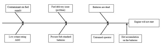
Figure 1 Fishbone Diagram For Ignition System Sub-System |
Figure 2
|
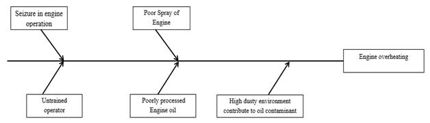
Figure 2 Fishbone Diagram for Cylinder Block Assembly Sub-System |
Figure 3
|
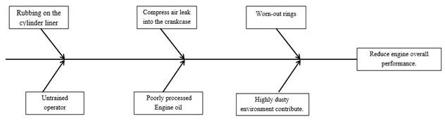
Figure 3 Fishbone Diagram for Piston and Connecting Rod |
Figure 4
|
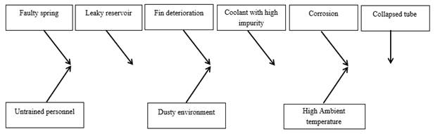
Figure 4 Fishbone Diagram for Engine Cooling System Sub-System |
The is section explained various ishikawa diagrams that gives pictorial representation of the understudied causes and effects for 365 KVA caterpillar generator subsystem. Below are the detailed explanations:
In considering Figure 1 as result of the researched, the effect is that the Engine will not start and underlisted are root caused which every operator and maintenance engineers, technicians etc should quickly ponder about:
Contamination on fuel supply. For a generator to run efficiently, from the process of conveying the AGO from loading depot proper tank inspection should be carried to see that AGO Tanker is free from raw food stuff particles, low-pour fuel oil, toxic chemicals and tank storage for servicing of the generator should be cleaned every four years and generator fuel filters should be replaced during servicing in compliance with Original Equipment Manufacturer (OEM) running hours instruction manual. This brings to limelight that all aspect of running engineering equipment should handle by professional engineers, so as to reduce frequent equipment breakdown to almost zero.
· Fuel delivery problem: proper checks should be carried out to confirm the flow of AGO to the injector, immediately so as reduce continuous cranking AGO starved engine. These equipment checks should be carried out by trained and experienced mechanical engineers to do necessary checks if there is AGO in generator tank, supplying pipes tracing to check if there are leakages to mention just a few.
Batteries are dead. Since the generator batteries rating are 12V, 200AH and they are two numbers, there is need to call the electrical maintenance engineers to confirm the status of each battery and also during the cranking process if 24V is still what the batteries are reading. There is need for proper checking of equipment, especially for Northern Nigeria in the dry season dust encroachment/invasion is very high and there should be culture of cleaning of the generator and batteries terminals in order to avoid impartial contact and short-circuiting. More so companies should buy original caterpillar batteries or Korea batteries that Korea is properly engraved on the battery. To save the engineering profession, professional engineers should stick on using original parts at all times.
Low octane rating AGO. AGO otherwise called diesel should be procured from approved loading depots where quality assurance for all the features for high performance diesel are being sold. It will enhance the starting process of the generator.
· Untrained operator. For sake of making the generator to run effectively and efficiently and save money, there is need for companies to send theirs operators and engineers on yearly basis to their major Original Equipment Manufacturers (OEMs) for training on preventive maintenance procedures that will reduce equipment failure to zero.
Considering Figure 2 shown above, the effect is that it lead to Engine overheating and the underlisted are root caused which every operator and maintenance engineers, technicians etc: should take necessary precautions. The root causes are listed below:
· Poorly processed engine oil: Engine oil that would be used for generator engine should from tested, approved by Standard Organization of Nigeria (SON) and from a reliable manufacturer, Total Tractagri HDX 15W-40, Kinematic viscosity at 100° C , HDX-40 and these engine oil safety data sheet and product informations datasheet should be properly studied to confirmed the necessary requirement for specify engine oil that produce best performance on the engine.
· Untrained operator. Generator operators need proper training and retraining in order to make the generator run effectively and efficiently. Companies should engaged special consultant with required expertise on the specific generators that are in used within the company, so that (OEM) Original Equipment Manufacturers can train the operators on preventive maintenance procedures that will elongate the equipment life span.
· High dusty environment: dipstick, engine oil and sump engine cover should be properly cared for, and dust prevention measures should be maintained to avoid dust ingress. Generator flushing using water should be a weekly exercise because of highly dusty nature of the Northern Region of Nigeria.
· Poor spray of engine oil: since the engine is experiencing overheating the engine oil will be drying up thereby causing engine oil starvation. The engine cooling system should be properly monitored by the operator by checking at the functionality of the fan, coolant and making sure standby generators runs for 8hrs before they are change -over in order the rate at which the seals.
· Seizure in Engine Operation: overheating leads to engine oil dry up that will cause engine oil starvation thereby making piston movement on the cylinder liner to be retarded and result to engine seizure. The cooling system should be properly checked whenever hourly reading si being taken. More so the radiator should have additional reservoir that is transparent for easy monitoring of coolant level. This will reduce failures cause by lack of coolant on the engine jacket thereby causing seals to burn leading to emulsification of the engine oil.
In view of Figure 3 above, the piston and connecting rod sub system plays and important roles in overall performance of an engine, if the vital components failed to work effectively and efficiently, it was observed that overall engine performance will be reduced drastically. Below are some that causes of engine low performance:
· Rubbing on the cylinder lining: when there is continuous rubbing on the cylinder lining due oil starvation, it will cause serious clearance and compress air will definitely leak to the crankcase thereby reducing carrying capacity of the engine.
· Compress air leak into the crankcase. Leaking of compress air is a sign that the clearance between piston and cylinder liner has widen which will lead to reduction in engine delivery power, frequent shortage of engine oil and emission of bluish smoke in the exhaust. In the ideal case when such situation occurs there is urgent need to derate the loading capacity of the equipment but due to ignorance in cause of loading to full capacity, the equipment failure rate will increase astronomically thereby resulting in high cost of maintenance that if proper comparison between the cost and benefit of repairs and replacement is carried-out, replacement could have been the best option.
· Worn-out piston rings: Constant misfires, rough idling, and poor acceleration all can be associated with various different problems but together they can be one of the common symptoms of worn piston rings. With a loss in compression pressure, the combustion process will be all over the place.
· Untrained operator. The effect of not having a trained operators cannot be overemphasized, a trained operator should be able to identify common problems that leads to breakdown such as:if coolant shorting excessively, there is no need of increasing the generator loading capacity and need to invite the maintenance department and report to Management that what he or she is observing might lead to serious breakdown and there is urgent need for intervention.
In considering Figure 4 above the underlisted and explained are the root causes of engine high temperature otherwise called overheating. They are: Faulty spring: engine that the thermostat have not been removed tend to have weak spring that stop coolant flow to the engine jackets for cooling of the engine. Manufacturers of engine usually project the maximum operating temperature to be 250C but here in Lokoja, Kogi State in Nigeria, we have temperature readings up to 400C as ambient temperature. It is advisable to remove engine thermostat in order to allow the engine have coolant at all times. More so we have never experienced temperatures like -20C in which the need to rise the temperature very fast in which the thermostat could play that significant role. Proper inspection should be carried to know the status of the thermostat every six months to confirm its operating position.
· Leaky coolant resevior (radiator): shortages of coolant on daily basis is a sign that the coolant is leaking for new engine but for an old engine it is due overheating and possibly leakages. It is advisable to report shortages of radiator coolant, so that early identification and prevention will save the equipment from having breakdown.
· Radiator fin deterioration: by using high pressure air to clean the radiator fin tend to destroy the fins opening for easy cooling of coolant tubes, during the cleaning process, it is advisable to used air pressure that will not bend the fins, because it can lead to overheating of the engine.
· Untrained personnel: operators of engine should properly trained to take note of little variation in operating temperature of an equipment to identify what might leads to those variation. If your generator is operating at 950C it is clear that generator is not working at a safe temperature and that generator should be shut down for proper troubleshooting. It is expected that both the Management and the maintenance department should be informed and proper overhaul that will identify the root cause of the generator should be carried out.
· Corrosion: coolant used on the generator should be treated water that does not have salt content and other minerals inside because any untreated water that is being used as coolant will lead to serious rusting on engine jacket and having accumulation of sludges on the radiator. This will lead to overheating of the engine.
· Collapsed tube: there is need for proper inspection and washing of radiator on six months basis in order to establish the fact that the radiator is free from debris and other sludges which may block coolant free flow there causing excessive overheating that will leads to the collapse of tube.
· Coolant with impurity: for equipment to last long, we should avoid using anyhow water on the engine radiator. Water with high level of impurity tend to increase level of corrosion and sludges build up in an engine.
4. CONCLUSION
The pictorial representation of causes and their effects will aid the maintenance team to have wider and timely troubleshooting to identify all the likely causes of failures and possible solution that solve the problem in a more proactive manner. More so in considering the ignition system sub-system, piston and connecting rod system sub-system, and engine cooling system sub-system it has provided easy working tool for the operators and maintenance beyond the generator manual to enable easily visualize the problem at handle and the likely root causes without spending hours, days trying to dust and peruse voluminous manual.
CONFLICT OF INTERESTS
None.
ACKNOWLEDGMENTS
None.
REFERENCES
Faiq, M. S. A., Ibrahim, A. M., and Ibrahim, F. V. (2018). Diagnosing The Causes of Failure in The Construction Sector Using Root Cause Analysis Technique, Hindawi. Journal of Engineering, 2018, 1. https://doi.org/10.1155/2018/1804053.
Kumar, M. P., Krishna, M., Raju, N. V. S., and Satish,
M. V. K. (2018). Failure Criticality Analysis Using Ishikawa Diagram
(A Case Study of Dumpers at Ocp,
Ramagundam). International Journal of Creative Research Thoughts (IJCRT), Ist National Conference on Trends
In Science, Engineering and Technology, 2nd–3rd Feb., 2018 Matrusri Engineering College, Saidabad, Hyderabad-500
059, 378.
Luca, L. (2016). A New Model of Ishikawa
Diagram for Quality Assessment.
Materials Science and Engineering. 20th Innovative Manufacturing
Engineering And Energy Conference (IManEE 2016). IOP Publishing IOP Conference Series, 161, 012099,
1.
Mario, C. (2017). The Fishbone Diagram To Identify, Systematize and Analyze the Sources of General Purpose Technologies. Journal of Social And Administrative Sciences, 4(4), 291–303.
Masoud,
H. (2011). The Application of Cause and Effect Diagram In The Oil
Industry In Iran : The Case of Four Liter Oil Canning Process of Sepahan Oil
Company. African Journal of Business Management, 5 (26), 10900–10907. https://doi.org/10.5897/ajbm11.1517.
Muhaiminul, I., Sultana, N., Sarker, T. P., And Ashiqur, R. (2016). Application of Fishbone Analysis for Evaluating Supply Chain and
Business Process- A Case Study on Kmart.
Industrial Engineering Letters,
6(7), 36.
Ravi, S. R., and Yadavalli, B. (2019). Quality Improvement of Capacitors Through Fishbone and Pareto Techniques. International Journal of Recent Technology and Engineering (IJRTE), 2277-3878, 8(2), 2248.
Shinde, D. D., Ahirrao, S., and Prasad, R. (2018). Fishbone Diagram : Application to Identify the Root Causes of Student–Staff Problems in Technical Education. Wireless Personal Communications, 100(2), 653–664. https://doi.org/10.1007/s11277-018-5344-y.
Ståhl, J. -E., Gabrielson, P., Andersson, C., and Jönsson, M. (2012). Dynamic Manufacturing Costs- Describing the Dynamic Behaviour of Downtimes from A Cost Perspective. CIRP Journal of Manufacturing Science And Technology, 5(4), 284–295. https://doi.org/10.1016/j.cirpj.2012.09.003.
Tarun, K. B. (2012). Application of Fishbone Analysis for Evaluating Supply Chain and Business Process- A Case Study on The St James Hospital. International Journal of Managing Value and Supply Chains (IJMVSC), 3 (2), 18.
|
|
 This work is licensed under a: Creative Commons Attribution 4.0 International License
© IJETMR 2014-2023. All Rights Reserved.