
|
|
|
|
New type of Glueing of Redox Flow Stacks
Thorsten Hickmann 1![]() , Prassad Venkatesan 1
, Prassad Venkatesan 1![]() , Martin Engelke 1
, Martin Engelke 1![]() , Nyunt Wai 2
, Nyunt Wai 2![]() , Falko Mahlendorf 3
, Falko Mahlendorf 3![]() , Aleksej Jasincuk 3
, Aleksej Jasincuk 3![]() , Ravendra Gundlapalli 4,
Arjun Bhattarai 4
, Ravendra Gundlapalli 4,
Arjun Bhattarai 4![]() , Ravi Ranjan 4
, Ravi Ranjan 4![]() , Purna C. Ghimire 4
, Purna C. Ghimire 4![]()
1 Eisenhuth GMBH & Co. KG,
Friedrich-Ebert-Str. 203, 37520, Osterode Am Harz, Germany
2 Energy
Research Institute, Nanyang Technical University, 637141, Singapore
3 Department
Energy Technology, University Duisburg-Essen, 47057, Duisburg, Germany
4 VFlowTech Pte Ltd, 8 Cleantech Loop #06-62, 637145, Singapore
|
|
|
ABSTRACT |
|
|
For the energy
transition to succeed, the growing amount of solar and wind power need to be
stored for night-time or low-wind periods. Redox flow storage offers a good
way of balancing out the fluctuations in renewable energies and is considered
a promising energy storage system because it is potentially inexpensive and
relatively easy to scale. However, the costs are still too high for this
technology to be a resounding success. New manufacturing and joining
technologies can help here. This will be demonstrated using the central
element of the redox flow battery, the stack, as an example. Here, novel
bonding ideas will be investigated and explained. The aim was to improve the
contact between the gas diffusion fleece on the active side of the bipolar
half plates and the current collector on the bipolar edge plates. A media and
temperature-resistant adhesive was tested and tried out in different geometries. |
|||
|
Received 01 August 2022 Accepted 01 September 2022 Published 15 September 2022 Corresponding Author Thorsten
Hickmann, t.hickmann@eisenhuth.de DOI10.29121/ijetmr.v9.i9.2022.1221 Funding: The work here
arose from the German-Singapore project "High Power Flow Battery".
From the German side, it was funded within the framework of the ZIM-AIF under
the funding code ZF4090604DN9. From
Singapur's side, it was developed under Enterprise Singapore Board
("Enterprise Singapore") under Enterprise Singapore Development
grant Application No.: 2004A3N8. Copyright: © 2022 The
Author(s). This work is licensed under a Creative Commons
Attribution 4.0 International License. With the
license CC-BY, authors retain the copyright, allowing anyone to download,
reuse, re-print, modify, distribute, and/or copy their contribution. The work
must be properly attributed to its author.
|
|||
|
Keywords: Redox Flow,
Stack, Glueing, Energy Conversion, Cost Reduction |
|||


1. INTRODUCTION
On the way to an era of renewable energies, resource conservation and reduction of emissions are a central issue for our society. This topic includes not only the generation of clean primary energy, for example from wind or sun, but also efficient conversion, safe intermediate storage and the development of decentralised supply to relieve the strain on the grids. In this context, not only will the share of renewable energies in electricity generation increase, but in particular also the share of fluctuating renewable energies, which cannot be regulated and thus pose a special challenge to the electricity grid and the future energy supply.
For intermediate storage – especially of electricity from fluctuating RE – over medium-term to longer periods (hours or days), conversion of electrical energy into chemical energy is the method of choice. A suitable technology for this is the redox flow battery. Skyllas-Kazacos (2010), Zhong and kyllas-Kazacos (1992), Qian et al. (2008) The main challenge with this technology is that the cost per kWh is still too high to achieve a rapid market penetration.
2. redox flow stacks
Redox flow batteries use solvent-based electrolytes in which active material (salts) are dissolved form. Anolyte and catholyte are kept in separate circuits with ion exchange across a membrane. The dissolved salt formers change their oxidation state by electron donation or absorption. This process determines the current flow as well as charging and discharging. State of research and development are numerous well-suited ionic variants, such as V2+/V3+ (negative pole) and V5+/V4+ (positive pole) in sulfuric acid. With this variant, unavoidable ionic leakage through the membrane into the other electrolyte does not result in permanent damage to the system. Only gradual performance degradation follows. Ponce et al. (2006) This makes this system an energy storage technology that is also suitable for non-stop and reliable applications.
The electrolytes are stored in separate tanks. If required, these electrolytes are fed to both sides of a reaction cell with pumps for the charging or discharging process. The energy densities of a redox flow battery are typically low (similar to lead-acid batteries). The reason is the limited solubility of vanadium salts in the sulfuric acid solvent. However, this is not a critical disadvantage for steady-state storage Sun and Skyllas-Kazacos (1992), Wang and Wang (2007). The central reaction unit is typically a membrane sandwich between the electrodes occupied by electrodes and works very similar to a hydrogen fuel cell (discharging) or an electrolyser (charging). The energy capacity of the battery is determined by the uptake volume of electrolyte solution in the tanks. Similar, the power output of the redox flow system is determined by the size of the charge/discharge cell. Trainham and Newman (1981), Shah et al. (2010)
Advantages of
redox flow system is mainly safety aspects over other types of batteries. For
example, lithium-based systems offer a higher potential hazard due to high
exothermic reactivity with oxygen and flammable organic solvents. In contrast,
dissolved vanadium salts of a redox flow system are not flammable in the
aqueous electrolyte system. Saleh (1999)
The reactions that take place in the battery are when discharging:
At the positive electrode:
V5+ + e– ⇌ V4+
or VO2+ + 2H+ + e– ⇌ VO2+ + H2O
At the negative electrode:
V2+ ⇌ V3+ + e–
Overall reaction:
V2+ + VO2+ + 2H+ + e– ⇌ VO2+ + V3+ + H2O
When loading, the reactions take place in the opposite direction. Hamilton and Pollet (2010)
Redox flow batteries were already intensively researched for stationary applications in the 1970s and 1980s. Trainham and Newman (1981), Shah et al. (2010), Saleh (1999) However, due to various material problems, activities were significantly reduced and only resumed in recent years due to the increasing demand for storage technologies. In principle, this battery technology is very well suited for large-scale use, as the construction of large tanks is not a problem. The electrolyte with the dissolved salt can be delivered easily and efficiently by tanker truck or rail. It should be emphasised here, however, that the redox flow storage system is a closed system, so that the electrolyte is not consumed, so that it has a service life of several years and can be reconditioned after this time Saleh (1999).
Among the possible electrochemical material combinations, the vanadium salt-based redox flow battery occupies a special position. Vanadium salts are used in both electrolyte spaces. These have different oxidation states to generate an electrochemical potential. Since the same element is used on both the cathode and the anode, cross-over effects between the electrolyte spaces are of secondary importance. Cross-over of vanadium from the anode to the cathode compartment or vice versa through a less than perfect membrane slightly reduces the electrochemical efficiency but does not lead to lasting damage or contamination of the system. This makes vanadium salt-based redox flow batteries a particularly robust variant.
3. glueinG trials
For the bonding and sealing of compound bipolar plates in pairs, an adhesive is to be designed and tested that can withstand and seal the occurring load cases within a stack system at a maximum of 0.5 bar electrolyte pressure. These applications and test series are also suitable for fuel cells Hamilton and Pollet (2010), Kreuz (2008), Heinzel et al. (2004). At this point, however, we will concentrate on the redox flow battery.
The adhesives were sampled according to a standardised sequence: (1) cutting of the electrodes; (2) deburring and dedusting of the surface on both sides; (3) cleaning of the adhesive groove with isopropanol; (4) application of an activator (if necessary); (5) application of the adhesive, if possible continuously, evenly; (6) pressing of both halves under load; (7) drying of the adhesive under load (if necessary); (8) determination of the adhesive properties by levering and splitting.
The following adhesives were tested:
Teroson MS 9399
Teroson PU 9225
Loctite Hy 4070
Sikaflex 221
Sikaflex 252
The following compounds were used together with the Standard Graphite-Compound, the so-called PPG 86 – Type EEE.
According to the data sheets, all the grades used have adhesive force properties that exceed the load occurring in the redox flow system.
3.1. Presentation of the results
In the following, the results will be presented in short form:
3.1.1. Teroson MS 9399
Teroson MS 9399 requires a lot of force to squeeze the adhesive out of the cartridge. The adhesive is not very flowable and is difficult to apply. After pressing and drying, the irregular shape of the application remains. Stability against twisting and bending seems to be present, as there is no peeling noise under such stress. The bond between the two panels is difficult to separate, even though the adhesive strip can be removed without residue and very easily. If a defect occurs, the entire joint pops apart.
In summary, the following can be stated: High force required for processing, not very flowable, pressing and drying irregular bonded areas visible, stable to torsion and bending, joint difficult to detach, easily separable if defective, very easy to remove without residue, adhesive very elastic.
3.1.2. Teroson PU 9225
The adhesive Teroson PU 9225 could be applied very well and quickly without much effort. After pressing, the entire adhesive groove was filled. An activator would be necessary to obtain a sensible adhesive strength. The bond between two panels is not stable enough and easily detached. The completely detachable adhesive strip appears friable and less elastic. The adhesion of the adhesive is mainly on the adhesive side. Further tests with roughening of the adhesive groove surface (320 grit sandpaper) or thermal heating after pressing showed that adhesion improves and is possible on both sides. Drying was carried out with a heat gun. However, this adhesion still does not seem to be stable enough. Cracking can be heard when the sheets are bent slightly, i.e., bonded areas come loose locally.
3.1.3. Loctite Hy 4070
Loctite Hy 4070 is jelly-like when applied and requires 24 hours of load-free curing time. Processing produced a slight eye irritation due to volatile vapours. The flowability is the best of all adhesives used and requires the least amount of force. Bonding points disappear, as adhesive seeks a common height level in the drawn bonding line. When dry, the adhesive is very brittle and fragile. The adhesive strip could be pulled off completely but not in one piece. Furthermore, the bonded electrodes cracked apart at low loads.
In summary, the following can be stated here: Consistency jelly-like, 24 hours load-free curing time, flowing application with little effort, build-up disappears, very brittle and fragile when dried, eye irritation due to volatile vapours.
3.1.4. Sikaflex 221/ 252
Sikaflex adhesives are summarised in this chapter as the differences were not very clear. The activators used initially appear to have a greater influence on the adhesive properties. Each of the two adhesives was tested with both activators and applied to electrode blanks. The processing was slightly worse than with Teroson PU 9225, but the adhesive was much more elastic and adherent when dry.
The respective activator (100 and 205) was applied with paper flow. The volatile vapours are very intense; therefore, the removal was done within a prepared closed environment (plastic bag with removal openings). The application points were placed well outside the glue line to avoid material thickening. The outlet nozzle should not be tapered, so a build-up on the electrode must be avoided, as the volume flow is relatively large. In addition, according to experience from this series of tests, adhesive should be applied to the outer edge of the adhesive groove, so that when pressure is applied, the adhesive does not spread into the flow field, but into the outer evasion areas.
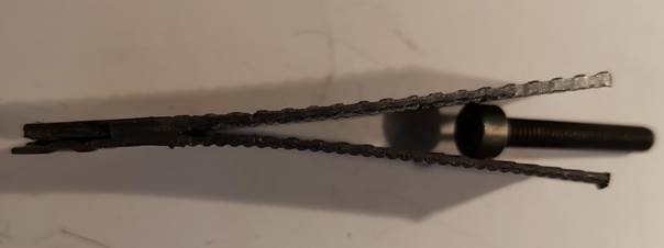
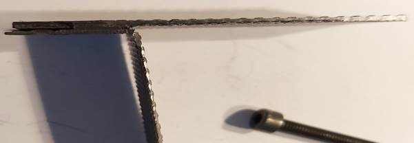
Furthermore, it turned out that the bonded joint must have a certain minimum thickness to be tested. Most of the bonded areas adhered very well; those areas with a thickness of 0.2 mm did not show any adhesion properties. Ultimately, in all combinations, the adhesions are subjectively sufficient and considerably better than those of the previously tested varieties. In the splitting test, no sample could be detached at the bonding point (Figure 1). All samples broke directly in front of the bonding point due to excessive bending stress.
|
Figure
1 Adhesive joint, expanded and
breakage of the plate |
In summary, the application was sufficiently good. There was an attachment point outside the adhesive groove and the application was carried out at the outer edge of the groove. The adhesion can be described as very good, no detachment without material breakage was possible. The activator vapour was very intense, so ventilation seems to be necessary.
This means that the Sikaflex 221/252 adhesive can be classified as suitable.
CONFLICT OF INTERESTS
None.
ACKNOWLEDGMENTS
None.
REFERENCES
Hamilton, P.J., and Pollet, B.G. (2010). Polymer Electrolyte Membrane Fuel Cell (PEMFC) Flow Field Plate : Design, Materials and Characterisation. Fuel Cells, 10(4),489-509. https://doi.org/10.1002/fuce.201000033.
Heinzel, A., Mahlendorf, F., Niemzig, O., Kreuz, C. (2004). Injection Moulded Low Cost Bipolar Plates for Pem Fuel Cells. Journal of Power Sources, 131(1-2), 35-40. https://doi.org/10.1016/j.jpowsour.2004.01.014.
Kreuz, C. (2008). PEM fuel Cells with Injection-Moulded Bipolar Plates Made of Highly Filled Graphite Compound. Dissertation, University of Duisburg-Essen.
Ponce de Leon, C., Frias-Ferrer, A., Gonzalez-Garcia, J., Szanto, D. A., Walsh, F. C. (2006). Redox Flow Cells for Energy Conversion. Journal of Power Sources, 160(1), 716-732. https://doi.org/10.1016/j.jpowsour.2006.02.095.
Qian, P., Zhang, H., Chen, J., Wen, Y., Luo, Q., Liu, Z., You, D., Yi, B. (2008). A Novel Electrode-Bipolar Plate Assembly for Vanadium Redox-Flow Battery Applications. Journal of Power Sources, 175(1), 613-620. https://doi.org/10.1016/j.jpowsour.2007.09.006.
Radforda, G.J.W., Coxa, J., Wills, R.G.A., Walshb, F.C. (2008). Electrochemical Characterization of Activated Carbon Particles Used in Redox Flow Battery Electrodes. Journal of Power Sources. 185(2), 1499-1504. https://doi.org/10.1016/j.jpowsour.2008.08.020.
Saleh, M. M. (1999). Mathematical Modelling of Gas Evolving Flow-Through Porous Electrodes. Electrochimica Acta, 45(6), 959-967. https://doi.org/10.1016/S0013-4686(99)00296-0.
Shah, A. A., Al-Fetlawi, H., Walsh, F. C. (2010). Dynamic Modelling Of Hydrogen Evolution Effects in the All-Vanadium Redox Flow Battery. Electrochimica Acta, 55(3), 1125-1139. https://doi.org/10.1016/j.electacta.2009.10.022.
Skyllas-Kazacos, M. (2010). History of the Development of the Vanadium Redox-Flow Cell. University of New South Wales.
Sun, B., and Skyllas-Kazacos, M. (1992). Chemical Modification of Graphite Materials for Vanadium Redox Flow Battery Application - Part Ii. Acid Treatment. Electrochimica Acta, 37(13), 2459-2465. https://doi.org/10.1016/0013-4686(92)87084-D.
Trainham, J. A., and Newman, J. (1981). A Comparison Between Flow-Through and Flow-By Porous Electrodes for Redox Energy Storage. Electrochimica Acta, 26(4), 455-469. https://doi.org/10.1016/0013-4686(81)87024-7.
Wang, W. H., and Wang, X. D. (2007). Investigation of Ir-Modified Carbon Felt as Positive Electrode of an all Vanadium Redox Flow Battery. Electrochimica Acta, 52(24), 6755-6762. https://doi.org/10.1016/j.electacta.2007.04.121.
Zhong, S., and kyllas-Kazacos, M. (1992). Electrochemical Behaviour of Vanadium (V)/vanadium (IV) Redox Couple at Graphite Electrodes. Journal of Power Sources, 39(1), 1-9. https://doi.org/10.1016/0378-7753(92)85001-Q.
|
|
 This work is licensed under a: Creative Commons Attribution 4.0 International License
© IJETMR 2014-2022. All Rights Reserved.