ShodhKosh: Journal of Visual and Performing ArtsISSN (Online): 2582-7472
|
|
Experimental Investigation of Newly Developed Electrolytic Magnetic Abrasive Finishing setup with multiple pole system for finishing of Alumium workpiece
Anil Malpotra 1![]() , Beant Singh 2, Lakhvir
Singh 3
, Beant Singh 2, Lakhvir
Singh 3
1 Research
Scholar, Department of Research and Development, IK Gujral PTU, Jalandhar,
Punjab, India
2 Professor
and Principal, Department of Mechanical Engineering, UIET, Lalru,
Punjab, India
3 Professor and Principal, Department of Mechanical Engineering, BBSBEC,
Fatehgarh Sahib, Punjab, India
|
|
|
ABSTRACT |
|
|
The procedure
of combining abrasion machining with chemical machining is the most demanding
and crucial method of machining, because it guarantees higher levels of
quality from the part. Combined procedure for machining are
typically employed as the last step in the machining process, and their
significance grows progressively crucial while a nano finished surface of the
work piece material is necessary. The subject of nano surface finishing of
materials via chemical machining and abrasion has advanced recently.
Electrolytic magnetic abrasive finishing (EMAF) is a procedure that combines
chemical and magnetic energy to achieve a desire finish. During the EMAF
process, The work piece fits in the middle among two
magnetic poles. A mixture of abrasives and ferromagnetic particles fills the
gap between each pole and the workpiece. The electrode is positioned at a
certain distance from the workpiece, and both are linked to a direct current
(DC) power source. An electrolytic solution is circulated between the gap using
a pump. The method offer a wide range of industrial
applications because to its low specific energy
consumption and enhanced surface finishing. This study presents the creation
of a novel EMAF with multiple pole system. It further looks into the impact
of different process attributes include machining time, rotational speed, size
of the abrasive particles, electrolytic concentration and weight of the
abrasive particles on the improved performance of material removal rate (MRR)
and surface finishing (PISF). |
|||
|
Corresponding Author Anil Malpotra, anil_malpotra@yahoo.co.in
DOI 10.29121/shodhkosh.v5.i1.2024.1747 Funding: This research
received no specific grant from any funding agency in the public, commercial,
or not-for-profit sectors. Copyright: © 2024 The
Author(s). This work is licensed under a Creative Commons
Attribution 4.0 International License. With the
license CC-BY, authors retain the copyright, allowing anyone to download,
reuse, re-print, modify, distribute, and/or copy their contribution. The work
must be properly attributed to its author.
|
|||
|
Keywords: Abrasion, ECM, MAF, EMAF |
|||


1. INTRODUCTION
Surface finishing is an essential component of production process with the goal of enhancing the visual and practical characteristics of materials. Conventional finishing techniques such as grinding, honing, abrasive machining and lapping frequently fail to achieve the needed level of precision and quality for advance applications [1-3]. The surface finish of a product has a direct impact on its lifespan and performance [4]. Sophisticated finishing techniques such as chemical mechanical polishing, magnetic abrasive finishing (MAF), and abrasive flow machining may be utilized to machine these components. [5]. However, these methods may have less productive result; MAF is a rigorous methodology applied to a work piece while it is under the magnetic field, causing material in the form of microchips to be eliminated [5–6]. In comparison with the MAF and ECM the EMAF proved the enhance results and save times [7]. To boost the effectiveness of the ECM process, the magnetic lines of force are integrated, causing a deviation from the straight course of the electrolytic ions and thus improving the efficiency of the machining [8]. By immediately decreasing the passive layer that builds up during the electrolytic process, the nonwoven abrasive pad increased the efficiency of the EMAF [9]. Nevertheless, the utilization of both electrolytic and magnetic abrasive meets the need for enhanced efficiency and improved surface. In this integrated procedure the abrasive particles efficiently eliminated the oxidized layer resulting from the electrolytic reaction, surpassing the effectiveness of the separate MAF. The interaction between the electric and the magnetic field causes negative ions to shift their orientation and move in a curved path towards the anode surface. This leads to an increase in the efficiency of the machining process [10].
2. DEVELOPMENT OF SETUP
This section described the newly developed EMAF with multiple pole system and the setup was investigated by considering different process variables during a test run experiment i.e. rotational speed of the workpiece, finishing time, electrolytic concentration, abrasive particle weight and the abrasive particle mesh size. The 4000 rotations per coil of copper binding were used to create the electromagnet of 17-gauge copper wire around 40mm diameter core which is made with the mild steel bar. Additionally, the magnetic poles are composed of mild steel, and figure 1 depicts the dimensions of the poles' design.
Figure1
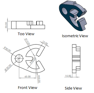
|
Figure 1 Design of Magnetic Poles |
A DC motor rotates the specimen between the magnetic poles. For the ECM, electrodes exist in the gap between the two magnetic poles, as shown in Figure 2. A separate DC supply has been provided and one end is connected with the electrode and the other is with the work piece and the electrolytic solution is flows in between the cavity of work piece and the electrode to complete the electrochemical process. Due to the chemical reaction the oxidation layer was formed on the surface of the specimen which the abrasive particles may remove with ease. The actual picture of the setup is shown in figure 3.
Figure 2
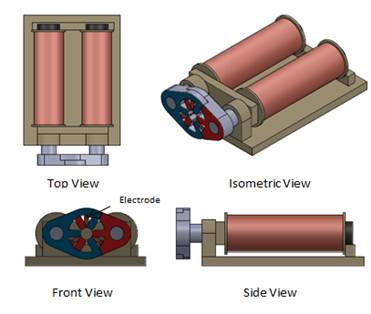
|
Figure 2 Different View of the EMAF Setup |
3. EXPERIMENTATION
The experimentation was conducted on the newly developed EMAF setup as shown in figure 3. Before commencing the experimentation, the surface roughness and weight of each specimen had been measured.
Figure 3

|
Figure 3 Actual Setu |
The nylon material was employed to secure the aluminum work piece onto the shaft of the DC motor. The abrasive elements occupy the space between the magnetic poles and the specimen. The positive terminal of the DC power supply touches the work piece, while the negative terminal connects to the electrode. A pump was used to supply the electrolytic solution from the reservoir to the gap between the work piece and the electrode required to complete the electrolytic process. Table 1 displays the parameters' range.
Table1
|
Table 1 Experimental Parameters for EMAF |
|
|
Parameter |
Range |
|
Machining Time |
10-60 min |
|
Workpiece Speed |
200-1000 rpm |
|
Electrolytic Concentration |
5-25 % |
|
% weight of abrasive |
5-25 % |
|
Mesh Size |
200-600 # |
4. RESULTS AND DISCUSSION
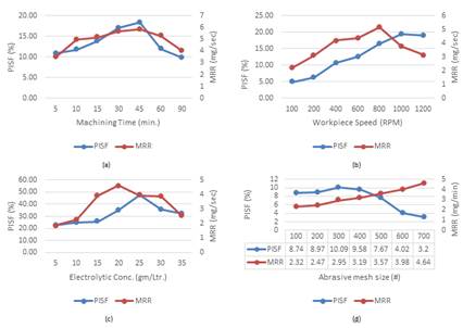
This segment provides an explanation of the results acquired from the preliminary experimentation. The experimentation was conceded out at a fixed workpiece speed of 600 rpm with an electrolytic concentration of 15 g/L, a 15% abrasive weight, and abrasive powder of 400 mesh size. Figure 4(a) depicts the effect of machining time. The figure shows that as machining time increases, the PISF gradually increases to 18.30% at 45 minutes, after which it decreases. This could be due to the increased time for the flexible brush to encounter the workpiece, resulting in improved PISF. Additionally, an increase in machining time initially leads to an increase in MRR, up to 5.86 mg/min with a machining time of 45 minutes, followed by a slight decrement.
Figure 4
|
Table 2 Effect of Various Input Parameters on PISF and MRR |
After that, the experimentation was carried out at different workpiece speeds by keeping other parameters constant: machining time at 30 minutes, electrolytic concentration at 15 g/L, weight of the abrasive at 15%, and mesh size of the abrasive particles at 400. Figure 4(b) illustrates that initially, as the workpiece rpm increased, the PISF also increased, reaching a maximum improvement of 19.41% at a speed of 1000 rpm. After that point, there was no further variation in the PISF. The abrasive particles' increased distance traveled during the machining process was responsible for the enhanced performance. Subsequently, the abrasive particles ceased to be effective in further enhancing the PISF. As the revolutions per minute reach 800 RPM, MRR increases. However, beyond this point, there is a significant decline in the MRR. This decrease may be due to the higher rotation of the workpiece causing damage to the sharp edges of the abrasive particles, resulting in a decrease in MRR.
Next, the experiment was conducted with a 30-minute machining time, 600 rpm workpiece speed, and 15% weight of abrasive powder with a mesh size of 400 abrasive particles at different electrolytic concentrations. Figure 4 (c) presents the results. According to the figure, the PISF improved to 47.69% at an electrolytic concentration of 25 g/L, after which it declined. This is because a higher electrolytic concentration promotes the chemical reaction, resulting in the production of a passive layer on the external of the workpiece. The abrasive powder's absorption effect subsequently eliminates this layer. Once a specific threshold is reached, any additional rise in concentration causes small cavity on the surface of the workpiece, resulting in a reduction of the PISF. When the electrolyte concentration is 20 g/L, MRR starts to increase and eventually reaches its highest value of 4.62 mg/min. It then decreases to a value of 2.54 mg/min at a concentration of 35 g/L. The abrasive powder effectively removes the passive layer on the workpiece at concentrations up to 20 g/L, which could explain this decrease. However, beyond that concentration, the abrasive particles fail to fully remove the passive layer, leading to a decrease in MRR.
Finally, the experimentation was done for different mesh sizes of abrasives by keeping the machining time of 30 minutes, the workpiece rotational speed of 600 rpm, the electrolytic concentration of 15 g/L, and a 15% weight of abrasive powder for each experiment. As depicted in Figure 4(d), the PISF improves as the mesh size of the abrasive elements decreases. The size of the abrasive particle is responsible for this improvement. The abrasive mesh size of 300 # resulted in a maximum improvement of 10.09%, while the PISF decreases below this range. This is due to the fact that larger particles result in more scratches on the workpiece surface, leading to a comparatively rough surface, while smaller particles result in a smoother surface. Reducing the mesh size results in a reduction in the MRR, implying a smaller elimination of material from the work piece surface compared to using abrasive particles with a larger mesh size. The larger particle has more cutting edges than the smaller one with a finer mesh size, which leads to a higher removal of material from the surface of the work piece.
5. CONCLUSION
This research examines the growth and development of newly EMAF machine and the preliminary experimentation was done to figure out the influence on distinct parameters like speed of the work piece, time for machining, electrolytic concentration, abrasive particle weight and the abrasive mesh size on PIAS and MRR. The following results can be concluded from the preliminary experimentation
1) The electrolytic concentration is having essential part in the improvement of the appearance of the work piece. As the higher electrolytic concentration boosting the efficiency of the setup.
2) The machine time is also having the impact on the PISF and MRR. PISF increases to 18.30% at the time of 45 minutes while the MRR was 5.86 mg/min for the same machining time.
3) Larger abrasive particles results in more scratches on the workpiece surface, leading to a comparatively rough surface, while smaller particles result in a smooth surface. With a lower mesh size, the MRR was lower.
CONFLICT OF INTERESTS
None.
ACKNOWLEDGMENTS
None.
REFERENCES
Jain VK. Advanced Machining Processes. New Delhi:Allied Publisher Pvt. Ltd. 2004.
P. Gupta, N. Ahamad, D. Kumar, N. Gupta, V. Chaudhary, S. Gupta, V.
Khanna, V.
|
|
 This work is licensed under a: Creative Commons Attribution 4.0 International License
© ShodhKosh 2024. All Rights Reserved.